Component check, Troubleshooting, Final assembly – Elenco Digital Roulette Kit User Manual
Page 11
-10-
COMPONENT CHECK
Make sure that all components have been
mounted in their correct places.
Make sure that the LED’s have been installed
correctly. The flat side of the LED’s should be in
the same direction as shown on the top legend.
Make sure that diodes D39 - D43 have not been
installed backwards.
The band on the diodes
should be in the same direction as shown on the
PC board.
Make sure that transistors Q1 - Q9 are installed
with their flat sides in the same direction as
marked on the PC board.
Are capacitors C5 - C8 installed correctly? These
capacitors have polarity. Be sure that the negative
lead is in the correct hole.
Make sure that the ICs are installed correctly. The
notch should be in the same direction as shown
on the top legend of the PC board.
Put a 9V alkaline battery into the battery holder
and push the switch.
TROUBLESHOOTING
One of the most frequently occurring problems is
poor solder connections.
1. Tug slightly on all parts to make sure that they are
indeed soldered.
2. All solder connections should be shiny. Resolder
any that are not.
3. Solder should flow into a smooth puddle rather
than a round ball. Resolder any connection that
has formed into a ball.
4. Have any solder bridges formed? A solder bridge
may occur if you accidentally touch an adjacent
foil by using too much solder or by dragging the
soldering iron across adjacent foils.
Break the
bridge with your soldering iron.
FINAL ASSEMBLY
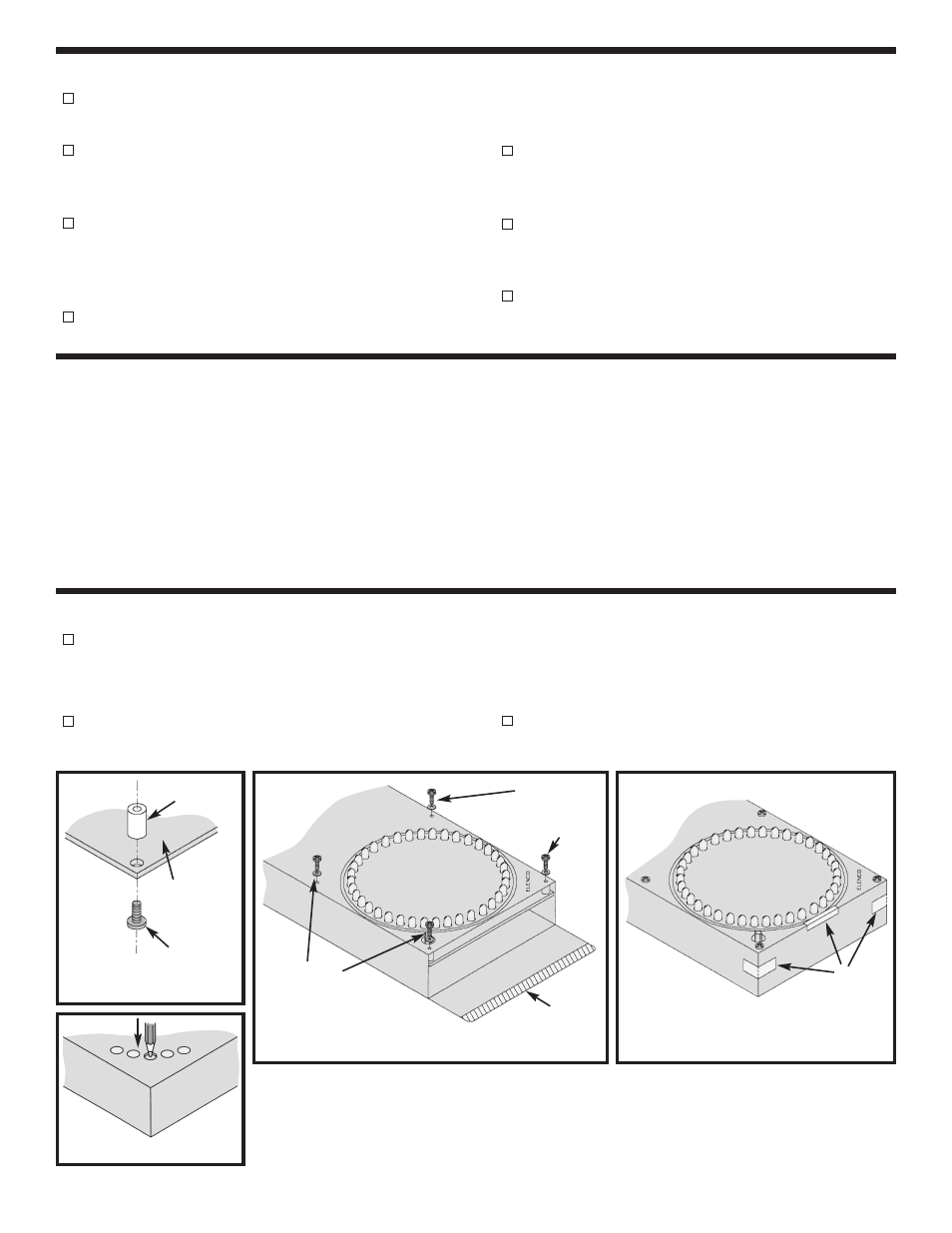
Mount the four plastic spacers onto the four
corners of the PC board from the foil side with four
4-40 x 1/4” black screws (see Figure I).
Punch out and save the chips from the box as
shown in Figure J. Slide the PC board into the box
and mount the PC board with four 4-40 x 1/4”
screws and four black washers (see Figure K).
Cut the strip off of the box as shown.
Tape the box lid shut (see Figure L) and you’re
ready to go!
Plastic Spacer
Legend Side of
PC Board
4-40 x 1/4”
Black Screw
Figure I
4-40 x 1/4”
Black Screws
and Black
Washers
4-40 x 1/4”
Black Screws
and Black
Washers
Figure K
Cut
Tape
Figure J
Figure L