Elenco Digital Roulette Kit User Manual
Page 5
-4-
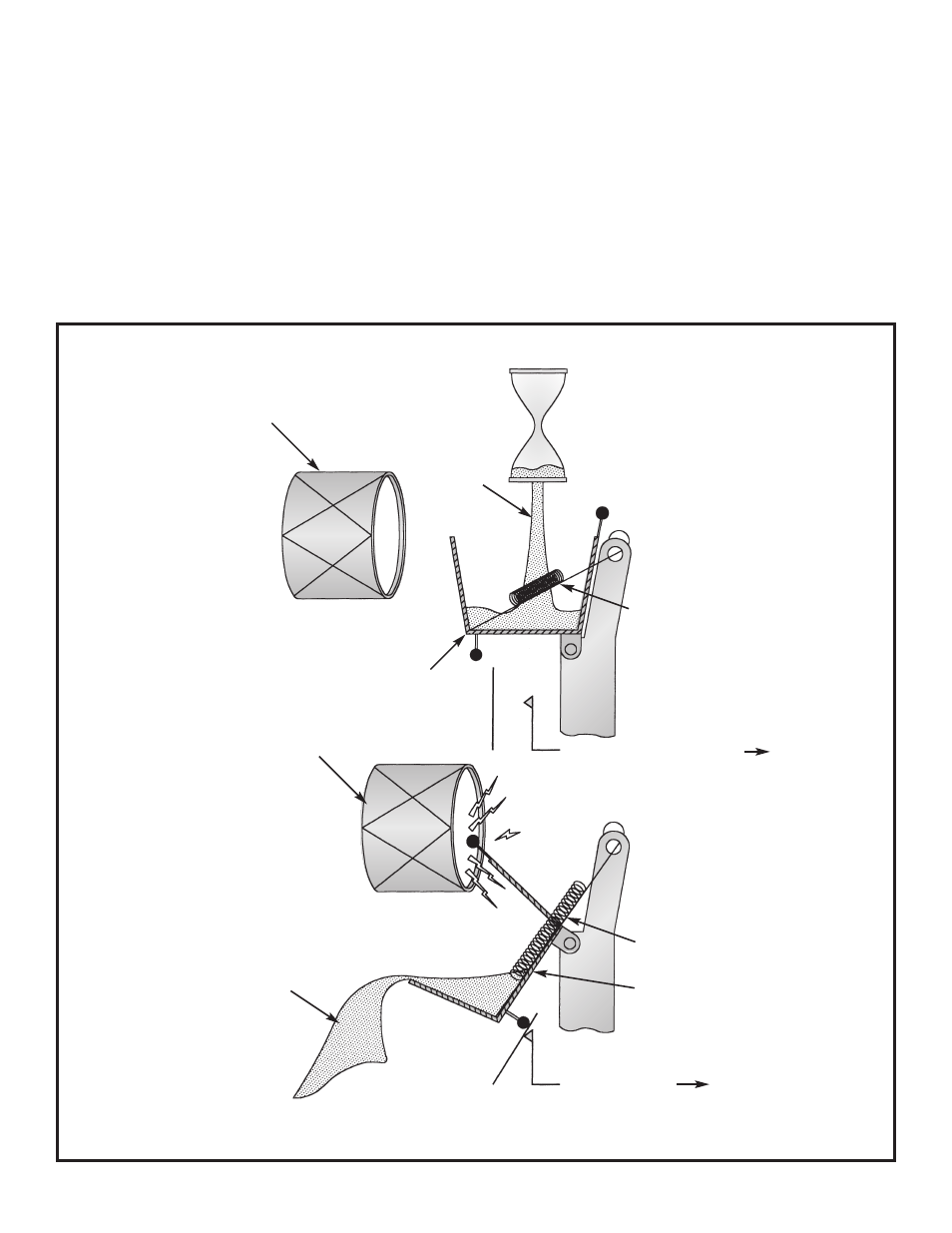
Assume that part of the sand from the “Timer Glass” in
Figure 2 is poured into a bucket as shown in Figure 3a.
When the bucket has enough sand, it will flip and
dump as shown in Figure 3b. Each time it flips, it
closes switch X2, sending the battery voltage to the
Ring Counter and it strikes the “Drum” producing a
sound. The bucket in Figures 3a & 3b represents
capacitor C6 in the schematic diagram on page 12.
Capacitor C6 charges (charging = filling the bucket
with sand) through resistor R20 and discharges
(dumping the sand) through resistor R19 and diode
D41. Each time the sand changes buckets, a pulse
is sent to the Ring Counter and to the Sound Circuit.
When the bucket is empty, the spring returns it to the
filling position shown in Figure 3a. The sand going
into the bucket will flow slower as the “Timer Glass”
in Figure 2 runs out of sand. It will take longer and
longer to fill the bucket as the sand runs out. This
produces more space between the pulses sent to the
ring counter and has the effect of slowing down the
rotation of the lights, similar to the ivory ball slowing
down on a roulette wheel.
THE PULSE GENERATOR
A
B
Drum for sound
Sand
Spring
Bucket
X2
Battery
Electrical Poles — 0 Volts To Ring Counter
Drum for sound
Spring
Battery Voltage To Ring Counter
Bucket
X2
Battery
Sand
Figure 3 Pulse Generator