Assemble components to the pc board, Led spacer, Figure h – Elenco Digital Roulette Kit User Manual
Page 10
R15 - 20k
Ω
5% 1/4W Resistor
(red-black-orange-gold)
R17 - 56k
Ω
5% 1/4W Resistor
(green-blue-orange-gold)
D42 - 1N4148 Diode
(see Figure E)
R24 - 270k
Ω
5% 1/4W Resistor
(red-violet-yellow-gold)
R18 - 3.3M
Ω
5% 1/4W Resistor
(orange-orange-green-gold)
R21 - 4.7M
Ω
5% 1/4W Resistor
(yellow-violet-green-gold)
Q9 - 2N3904 Transistor
(see Figure C)
Q8 - 2N3904 Transistor
(see Figure C)
Q6 - 2N3906 Transistor
(see Figure C)
S1 - Switch
BT - Battery Holder
BZ1 - Buzzer
3 Screw 2-56 x 5/16”
3 Nut 2-56 Hex
3 Flat Washer White
4” Wire 22 ga.
(see Figure H)
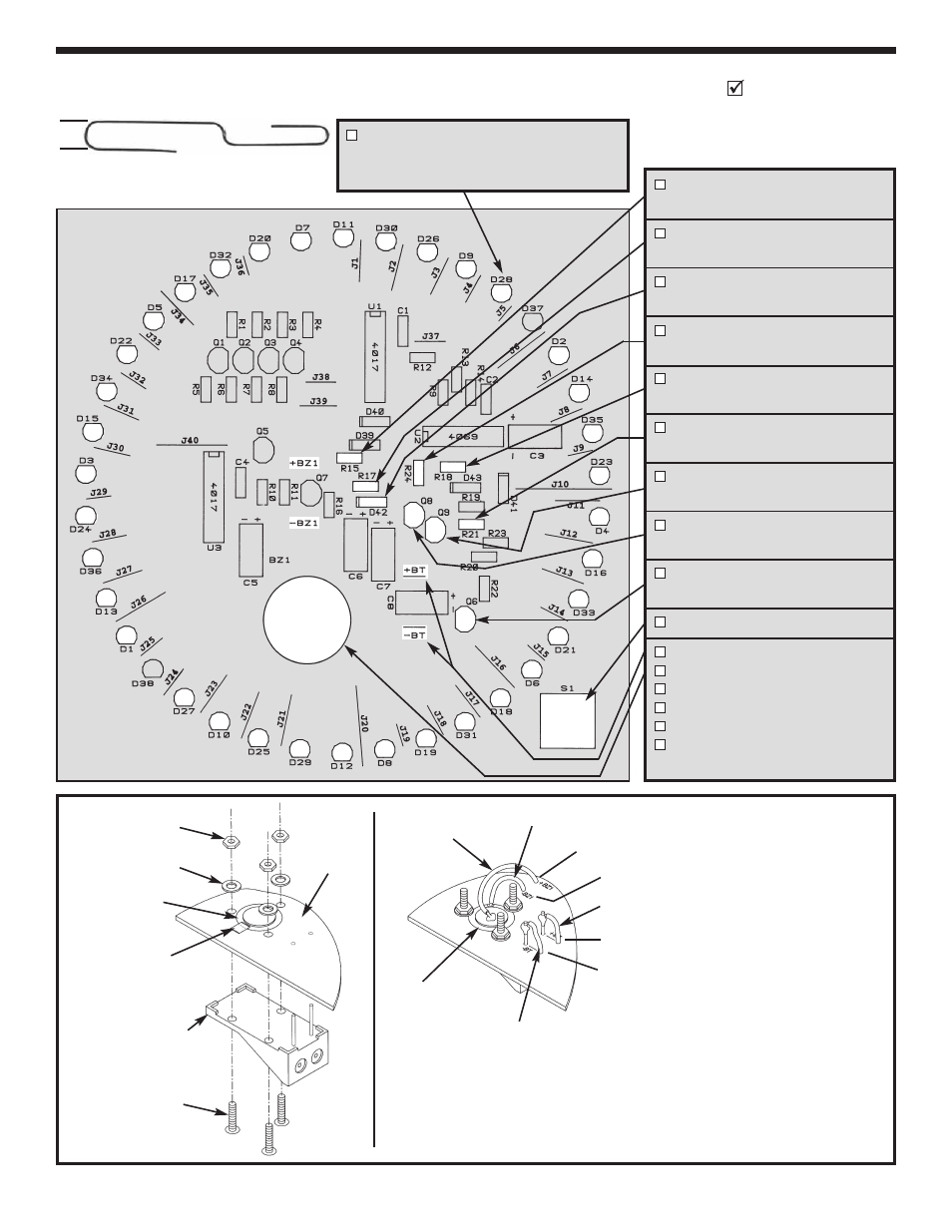
ASSEMBLE COMPONENTS TO THE PC BOARD
Identify and install the following parts as shown. After soldering each part, place a check in the box provided.
D1 – D36 - LED Red (be sure to note
the flat side when installing).
(see Figure A)
LED Spacer
(Actual Size)
1/4”
Figure H
Mount the battery holder and
buzzer to the PC board as
shown (1). Note: Use a piece of
Scotch Tape on the brass part
only to hold the buzzer in place.
Solder a 5/8” wire from the
positive (+) battery holder lead
to the +BT point on the PC
board (2).
Solder a 5/8” wire
from the negative (–) battery
holder lead to the –BT point on
the PC board. Solder a 1” wire
from the outer edge of the
buzzer to –BZ1. Solder a 1 1/2”
wire from the inner circle of the
buzzer to +BZ1. Note: Do not
let the flat washers touch the
silver part of the buzzer of let the
solder from the wire from the
outer edge touch the silver part.
1.
2.
Battery Holder
Scotch Tape
2-56 Hex Nut
Flat Washer
Buzzer
PC Board
Legend Side
2-56 x 5/16”
Screw
Buzzer
1” Wire
1 1/2” Wire
+BZ1
5/8” Wire
+BT
–BT
5/8” Wire
–BZ1
-9-