Warning, Caution – Dunkirk Excelsior EXB Series User Manual
Page 6
6
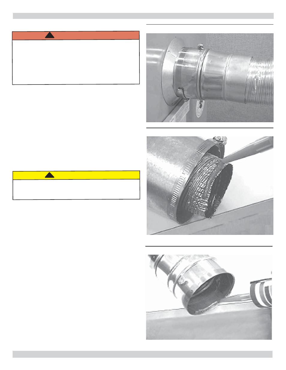
Figure 6 - Appliance Connector w/ Test Port
Figure 7 - Male End
Figure 8 - Female End
Venting Installation - Direct Vent
WARNING
Improper installation, adjustment, alteration, service
or maintenance could result in death or serious
injury. Do not enclose vent.
Do not route vent through walls, fl oors or ceilings.
Venting and vent terminal are dedicated to the Boiler
only; do not attempt to vent any other appliance
through it.
!
Flexible Vent Installation
Supplied fl exible exhaust duct is a double wall, one (1) inch
clearance to combustibles, fl exible venting material.
Inner pipe is constructed of 4 inch inside diameter 316
stainless steel, with two-ply aluminum outer pipe.
High temperature insulation separates inner and outer fl ex
pipes.
Vent installation shall conform to requirements of authority
having jurisdiction or in absence of such requirements NFPA
31 Installation Of Oil Burning Equipment (U.S.) or CSA
B139 (Canada) and applicable provisions of local building
codes and these instructions.
CAUTION
Use appropriate safety precautions. Thin metal
edges are extremely sharp. If not avoided, could
result in minor or moderate injury.
1.
In as short and straight a run as possible without any
unnecessary bends.
2.
No dips or sags throughout full length of vent.
3.
Slope connector or vent upwards from appliance at
least 1/4” per foot.
4.
Do not bend connector or vent more than 90°.
5.
May cut vent to a minimum of 5 feet in length using
fi ne tooth (24 teeth per inch) hacksaw blade.
6.
Clean male and female ends of the appliance adapters
and connectors with residue free brake cleaner solvent.
7.
Apply minimum 1/4” bead of Si-Ultra Copper Sealant
provided, onto outside of male end of vent to appliance
connector. Fit connector to vent by threading it
counter-clockwise until it stops. Insure joint is not
cross-threaded. Tighten gear clamp on outer cover. See
fi gures 7, 8 & 9.
8.
Apply minimum 1/4” bead of same sealant on female
end inside of connector. Slip connector over end of
appliance collar until it stops. Tighten attached gear
clamp. See Figure 8.
9.
Support Vent every 36” to prevent sagging.
10.
Attach Terminal Connector as described in steps listed
above.
11.
Maximum vent length is 20 feet (using 20 foot vent
kit). Piecing vent kits together (i.e. using 2 ten foot
kits) is strictly prohibited.
VENT PIPE INSTALLATION
!
!