Specifications, Application sizing and “rules of thumb, Description specification – Bimba PCS User Manual
Page 22
www.bimba.com
Technical Assistance: 800-44-BIMBA
22
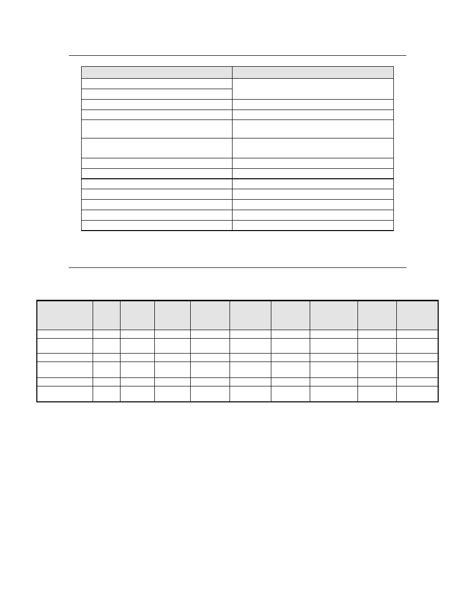
SPECIFICATIONS
Description
Specification
Zero Adjustment
50% of Total Full Scale Output between
both adjustments
Span Adjustment
DECEL Adjustment
Approximately 0.5 to 13.5 volts
Deadband Adjustment
Approximately 0.005 to 0.500 Volts
@ Position
Discrete signal that Sinks to Ground when
Within Deadband zone. 20mA Maximum.
Current Position
0 to 10 VDC signal, 1M ohm input
impedence required for input device.
Operation at Power Loss
All valves close at power loss.
Input Supply Voltage
23.5 to 24.5 VDC, 1 amp
Operating Pressure
70 to 80 psig
Air Requirement
Regulated and Filtered to 5 micron
Operational Temperature Range
0 to 100 degrees F (Electronics\PC Board)
Reverse Polarity Protected
Overvoltage Protected
APPLICATION SIZING and “RULES OF THUMB
PFC Cylinder/PCS Valve System Matching and Sizing Recommendations*
Bore Size
PCS
Model
Stroke
Range
Maximu
m
Payload
Average
Velocity
Maximum
External
Friction
Zero
Friction
Deadband
**
½ Maximum
Friction
Deadband
Maximum
Friction
Deadbead
Minimum
Step
PFC-09 (1-1/16") PCS-1
2" to 7"
1 lb
2.75 in/sec
zero
+/- 50mV
NA
NA
0.080"
PFC-09 (1 1/16") PCS-1 8" to 24"
30
pounds
4.00 in/sec
5 pounds
+/- 40mV
+/- 80mV
+/- 160mV
0.20 - 0.39"
PFC-17 (1-1/2")
PCS-1
1" to 3"
2 lbs
2.50 in/sec
zero
+/- 25mV
NA
NA
0.040"
PFC-17 (1 1/2")
PCS-2 4" to 24"
50
pounds
5.50 in/sec
10 pounds
+/- 20mV
+/- 40mV
+/- 80mV
2 times
Deadband
PFC-31 (2")
PCS-2
1" to 2"
4 lbs
2.75 in/sec
zero
+/- 50mV
NA
NA
0.020"
PFC-31 (2")
PCS-3 3" to 24"
90
pounds
6.50 in/sec
20 pounds
+/- 15mV
+/- 30mV
+/- 60mV
2 times
Deadband
*If your application requires lower velocities or payloads, you may be able to reduce
the minimum recommended deadband setting, or if your deadband requirements can
accommodate a large range, you may be able to increase your payload higher than the
recommended values.
**Note: Use the Formulas in the Glossary to convert the Minimum Deadband shown
in the table to displacement.
Assumptions used for Sizing Values recommended above:
• Values shown above are with no overshoot. If overshoot is acceptable for your
application, the Deadband may possibly be less than specified above. However,
be sure your system cannot go unstable. Refer to Caution statement on page 20.
• PFC cylinder with Option L is used. (Option L has very low friction seals. The
standard PFC utilizes a rod wiper which increases friction significantly, which
will have adverse effects on positioning capabilities).