Bimba PCS User Manual
Page 15
www.bimba.com
Technical Assistance: 800-44-BIMBA
15
Measure the voltage with a digital voltmeter at Terminal Block TB1
on the PCS PC Board. The voltage must be between 23.5 VDC and
24.5 VDC for the system to function properly.
10.
APPLY PNEUMATIC PRESSURE
Ensure the actuator is clear of all obstacles. Apply a low pneumatic pressure (20
psi). The actuator should attempt to move. If no command signal is applied to the
PCS, the cylinder will attempt to assume its zero position. Once the cylinder has
moved and stopped, raise the pressure to the normal operating pressure (70 to 80
psi). If the actuator does not move, it may already be at the zero position.
CAUTION!
If full system pressure is applied with a large error signal present,
the actuator will attempt to instantaneously move to the command
signal position. This could potentially cause physical harm or
damage to application tooling. Once system is installed, always
ensure that the command signal and feedback signal are equal at
start up or start system up at low pressure.
11.
SET THE “DEADBAND”
The Deadband should initially be set according to the Application Sizing Chart.
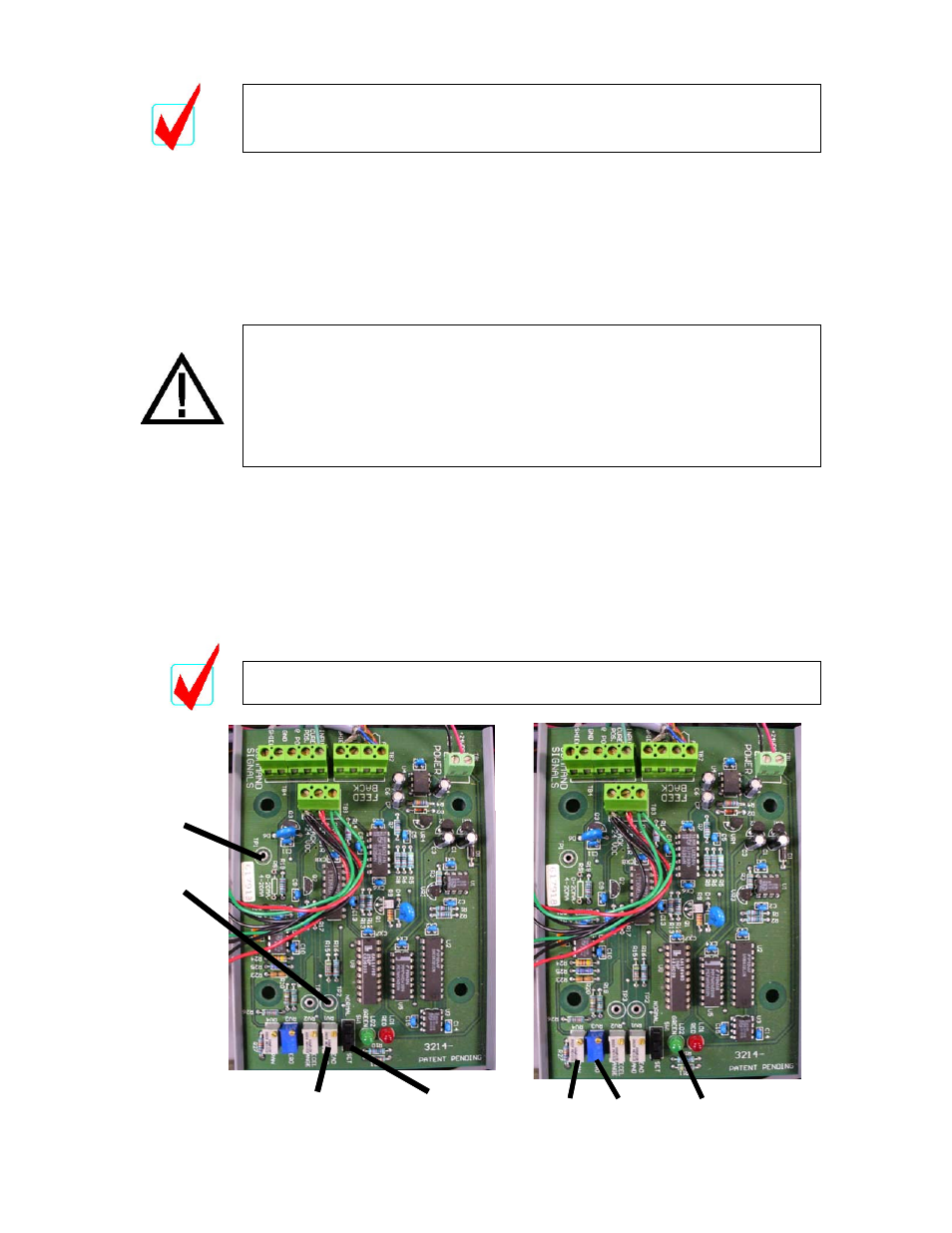
Move switch SW1 on the PC Board from the NORMAL to the SET position. (see
illustration on page 11 and the photo below). Set the digital voltmeter to DC volts
and measure the voltage between the Ground Reference Point (TP1) and TP2 on
the printed circuit board. Adjust the Deadband setting to the recommended
minimum voltage setting shown in the Application Sizing Chart.
After the Deadband is set, the SW1 Switch must be returned back to
the Normal position or the PCS will not function.
LED’s
Span
Zero
LED’s
Span
Zero
TP1
TP2
SW1
Deadband
TP1
TP2
SW1
Deadband
DEADBAND ADJUSTMENT
SPAND AND ZERO ADJUSTMENTS