Bimba PCS User Manual
Page 12
www.bimba.com
Technical Assistance: 800-44-BIMBA
12
Option Q
Connect the Quick Connect power cable (2 meter model PCS-CBL-PWR or 5
meter Model PCS-CBL-PWR-X) to power. Connect the other end of the cable
using the following color codes: +24 VDC-Brown, Ground-Blue, the other wires
are not used.
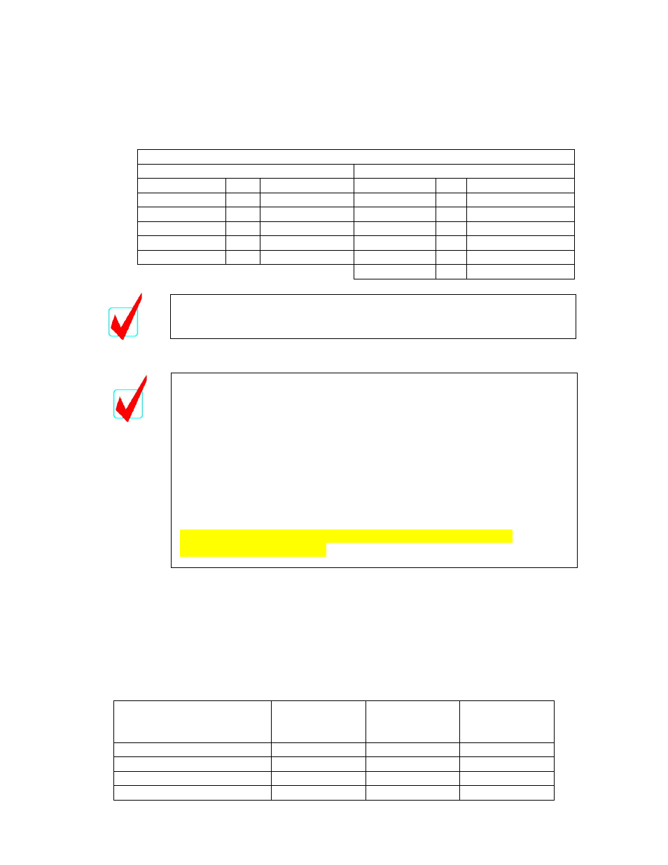
Quick Connect Wire Color Codes
Power cable PCS-CBL-PWR
Command Cable PCS-CBL-CMD
Color Pin
Description
Color
Pin
Description
Brown 1
Positive Brown 1
Input
White 2
N/C
White 2
@
Position
Blue 3
Negative
Blue 3
Ground
Black 4
N/C
Black 4
Current
Position
Green/Yellow 5 N/C
Gray
5 N/C
Pink
6
N/C
Do not allow the supply voltage to vary outside of the 23.5 to 24.5 voltage
specification, as this will degrade system response and performance
significantly.
5.
CONNECT THE FEEDBACK CABLE
Standard Enclosure
Connect the feedback cable from the actuator to the PCS. The OD of the cable
must be between 0.114 inch and 0.250 inch. If the actuator is equipped with a
plug connector, utilize accessory cable C5 or C5X. If the actuator has a pigtail
lead, attach a longer cable between the actuator and the PCS observing the color
standards shown in the table below. Pass the cable through the bulkhead strain
relief and connect the individual wires to terminal block TB2 on the PCS board.
Wire Function From
Feedback Device
Wire Color 3
Pin Connector
(C5 or C5X)
Wire Color
Pigtail Lead
PCS
Terminal Block
TB2
Input (Excitation Voltage)
Blue
Red
A
Feedback Signal
Brown
White
B
Ground Black
Black
C
Shield
Shield N/A Shield
For PFCN only
, power to the probe MUST come from 24 VDC supplied
to the PCS control, and NOT the 10 VDC that the PCS produces from
terminal A of TB2.
For PFCN only
, If the Q (quick connect) option was selected, the lead
from the connector to terminal A of TB2 must be removed and the lead
reinserted into the +24VDC terminal of TB1.
For PFCN only
, always insert a jumper between TB1 ground and TB2
terminal C.
See PFCN ELECTRICAL AND PNEUMATIC CONNECTIONS
illustration in APPENDIX A.