6 connecting dc power, 7 wall-mounting the mxe-5400, Connecting dc power – ADLINK MXE-5400 User Manual
Page 50: Wall-mounting the mxe-5400, Preliminary
PRELIMINARY
38
Getting Started
2.6
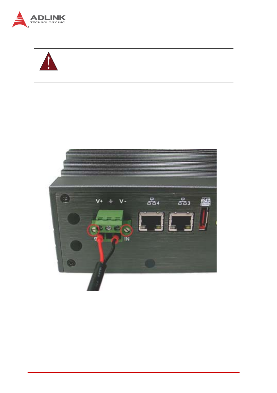
Connecting DC power
The DC power input connector of the MXE-5400 utilizes V+, V- ,
and chassis ground pins, and accepts input voltage as shown pre-
viously.
1. Connect DC power.
2. Fix the DC connector using the 2 screws.
2.7
Wall-mounting the MXE-5400
The MXE-5400 is shipped with wall-mount brackets and acces-
sory screws, with mounting procedures as follows.
1. Prepare the two wall-mount brackets and 4 M4-P head
screws included in the package.
WARNING:
Before introducing DC power to the MXE-5400, ensure the
voltage and polarity provided are compatible with the DC input.
Improper input voltage and/or polarity can be responsible for
system damage.
See also other documents in the category ADLINK Hardware:
- USB-1901 (84 pages)
- USB-1210 (54 pages)
- USB-2401 (60 pages)
- USB-7230 (50 pages)
- USB-2405 (56 pages)
- DAQe-2010 (92 pages)
- DAQe-2204 (100 pages)
- DAQe-2213 (94 pages)
- DAQe-2501 (74 pages)
- PXI-2010 (84 pages)
- PXI-2020 (60 pages)
- PXI-2501 (62 pages)
- cPCI-9116 (98 pages)
- ACL-8112 Series (93 pages)
- ACL-8112 Series (94 pages)
- ACL-8112 Series (92 pages)
- ACL-8216 (75 pages)
- ACL-8111 (61 pages)
- PCM-9112+ (10 pages)
- PCM-9112+ (94 pages)
- cPCI-6216V (47 pages)
- ACL-6126 (28 pages)
- ACL-6128A (40 pages)
- PCM-6308V+ (52 pages)
- PCM-6308V+ (4 pages)
- PCI-7444 (82 pages)
- PCI-7434 (48 pages)
- PCI-7234 (56 pages)
- PCI-7260 (66 pages)
- PCI-7258 (38 pages)
- PCI-7256 (48 pages)
- PCI-7250 (48 pages)
- LPCI-7250 (48 pages)
- PCI-7396 (65 pages)
- PCI-7296 (59 pages)
- PCI-8554 (67 pages)
- PCIe-7360 (94 pages)
- PCIe-7350 (86 pages)
- PCIe-7300A (114 pages)
- PCIe-7200 (51 pages)
- PCI-7300A (83 pages)
- PCI-7300A (112 pages)
- PCI-7200 (96 pages)
- cPCI-7300 (82 pages)
- cPCI-7300 (83 pages)