1 clear cmos jumper, 2 dc 5v and 3.3v connectors for gps module, Clear cmos jumper – ADLINK MXE-5400 User Manual
Page 35: Dc 5v and 3.3v connectors for gps module, Table 1-13, Clear cmos jumper pin assignment, Figure 1-18, Clear cmos jumper pin settings, Preliminary
PRELIMINARY
Introduction
23
MXE-5400
1.8.1
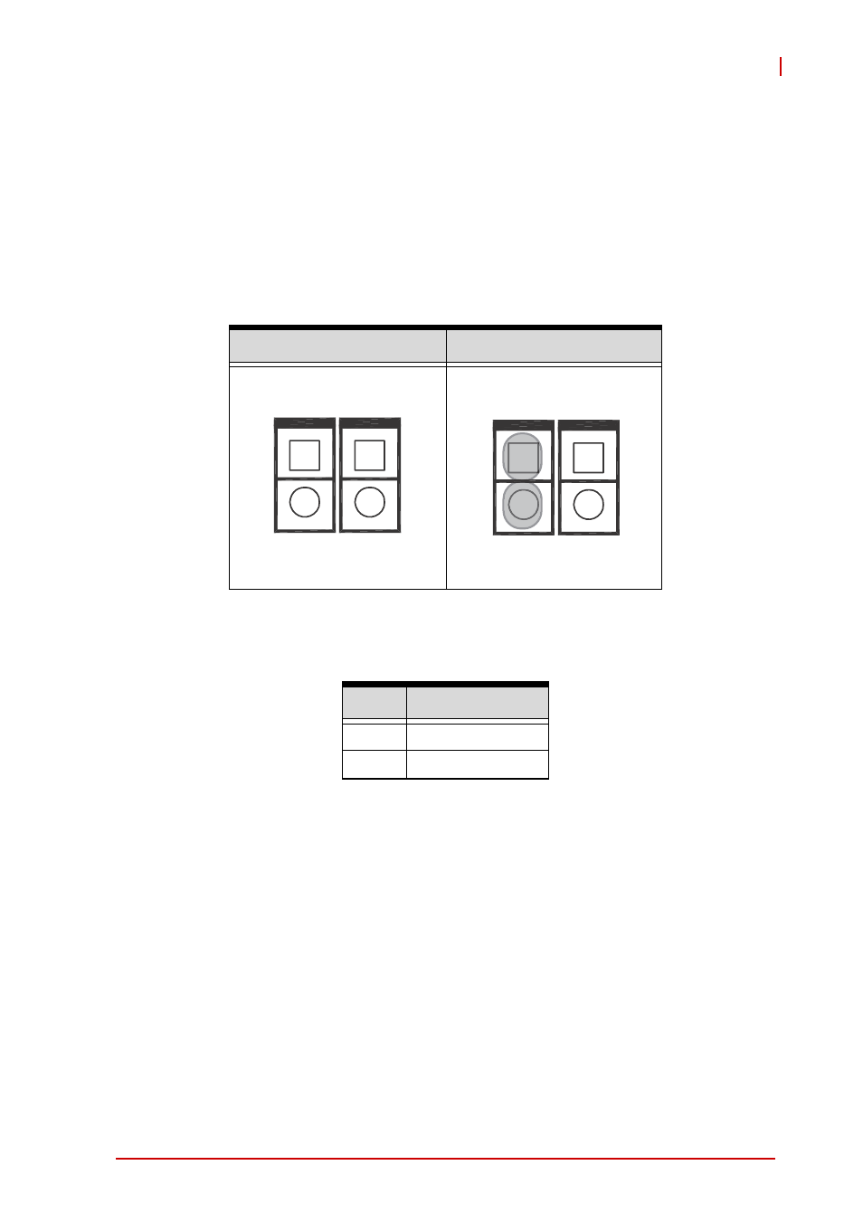
Clear CMOS Jumper
Under conditions in which the MXE-5400 fails to boot, clearing the
BIOS content stored in CMOS and restoring the default settings
may be effective. To clear CMOS, short Pin#1 and Pin#2 of CN3
and remove the jumper, after which the CMOS will be restored to
factory default settings.
Figure 1-18: Clear CMOS Jumper Pin Settings
Table 1-13: Clear CMOS Jumper Pin Assignment
1.8.2
DC 5V and 3.3V Connectors for GPS Module
The two power connectors, for GPS module use, carry a maxi-
mum current rating of 1A each.
Normal
Clear
Pin
Description
1
RTCRST#
2
Gnd
CN3 CN4
1
2
1
2
CN3 CN4
1
2
1
2
See also other documents in the category ADLINK Hardware:
- USB-1901 (84 pages)
- USB-1210 (54 pages)
- USB-2401 (60 pages)
- USB-7230 (50 pages)
- USB-2405 (56 pages)
- DAQe-2010 (92 pages)
- DAQe-2204 (100 pages)
- DAQe-2213 (94 pages)
- DAQe-2501 (74 pages)
- PXI-2010 (84 pages)
- PXI-2020 (60 pages)
- PXI-2501 (62 pages)
- cPCI-9116 (98 pages)
- ACL-8112 Series (94 pages)
- ACL-8112 Series (92 pages)
- ACL-8112 Series (93 pages)
- ACL-8216 (75 pages)
- ACL-8111 (61 pages)
- PCM-9112+ (10 pages)
- PCM-9112+ (94 pages)
- cPCI-6216V (47 pages)
- ACL-6126 (28 pages)
- ACL-6128A (40 pages)
- PCM-6308V+ (52 pages)
- PCM-6308V+ (4 pages)
- PCI-7444 (82 pages)
- PCI-7434 (48 pages)
- PCI-7234 (56 pages)
- PCI-7260 (66 pages)
- PCI-7258 (38 pages)
- PCI-7256 (48 pages)
- PCI-7250 (48 pages)
- LPCI-7250 (48 pages)
- PCI-7396 (65 pages)
- PCI-7296 (59 pages)
- PCI-8554 (67 pages)
- PCIe-7360 (94 pages)
- PCIe-7350 (86 pages)
- PCIe-7300A (114 pages)
- PCIe-7200 (51 pages)
- PCI-7300A (112 pages)
- PCI-7300A (83 pages)
- PCI-7200 (96 pages)
- cPCI-7300 (82 pages)
- cPCI-7300 (83 pages)