4 switch and jumper settings, Sw1 & sw4 (debug use only), Mode switch (sw2) – ADLINK CT-61 User Manual
Page 35: Switch and jumper settings
Board Interfaces
25
CT-61
4.4
Switch and Jumper Settings
Refer to “CT-61 Board Layout - Top Side” on page 15 and “CT-61
Board Layout - Bottom Side” on page 16 for switch locations.
SW1 & SW4 (Debug use only)
The switches SW1 & 4 are for debugging purposes and should
be left in the default settings. The default setting of SW1 is all
OFF; the default setting of SW4 is Pin 1 OFF and Pin 2 ON.
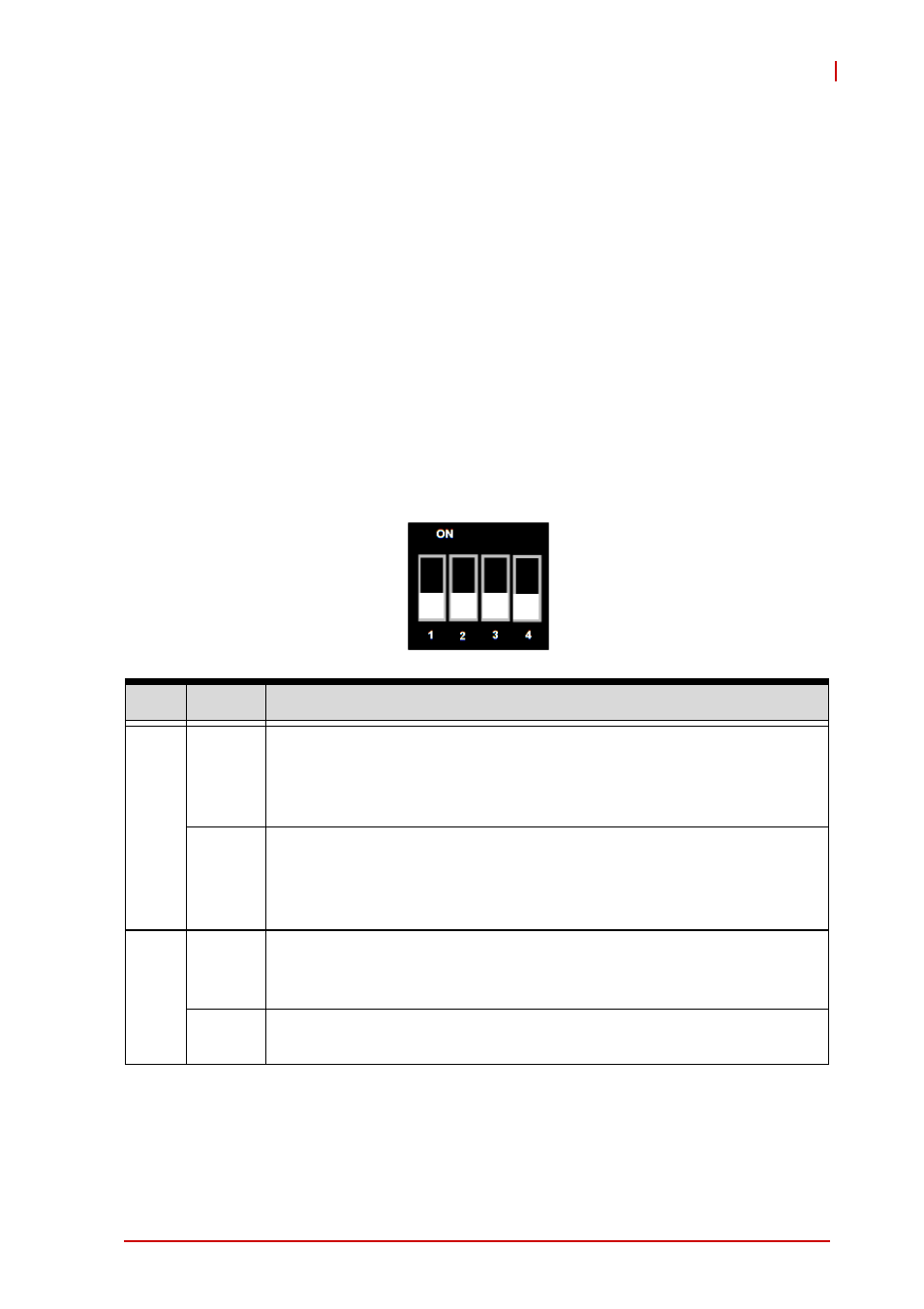
Mode Switch (SW2)
Switch SW2 is a multi purpose switch that allows users to
define the board operating mode. Four pins independently con-
trol the mode setting. All are set to OFF by default.
Pin#
Status
Description
1
OFF
Universal Mode: The CT-61 in a peripheral slot has CompactPCI
bus communication with the host board in the system slot. The
CT-61 can boot-up in a peripheral slot and be recognized by the
host board in the system slot as a PCI device.
ON
Satellite Mode: The CT-61 in a peripheral slot has no
CompactPCI bus communication with the host board in the system
slot. The CT-61 behaves a as standalone blade in the peripheral
slot.
2
OFF
When the system does not include a CMM (Chassis
Management Module), set this pin to OFF to allow IPMI to run in
"without CMM mode".
ON
When the system includes a CMM, set this pin to ON to allow
IPMI to run in "with CMM mode".