2 gpib connector, Gpib connector, Table 1-3: gpib pin description – ADLINK PXIe-3985 User Manual
Page 22
10
Introduction
1.3.2
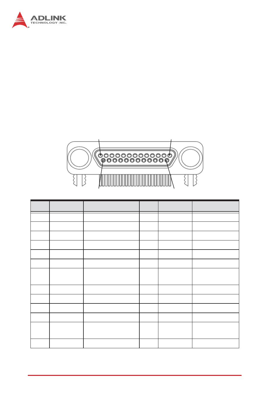
GPIB Connector
The GPIB connector on PXIe-3985 is a micro D-sub 25P connec-
tor, controlling external bench-top instruments. Connection to
other instruments requires the optional ACL-IEEE488-MD1-A
cable. The on-board GPIB controller provides:
X
Full compatibility with IEEE 488 standard
X
Up to 1.5MB/s data transfer rates
X
Onboard 2 KB FIFO for read/write operations
X
Driver APIs are compatible with NI-488.2 driver software
X
Connection with up to 14 instruments
Table 1-3: GPIB Pin Description
Pin
Signal
Description
Pin
Signal
Description
1
DIO1#
GPIB Data 1
14
DIO5#
GPIB Data 5
2
DIO2#
GPIB Data 2
15
DIO6#
GPIB Data 6
3
DIO3#
GPIB Data 3
16
DIO7#
GPIB Data 7
4
DIO4#
GPIB Data 4
17
DIO8#
GPIB Data 8
5
EOI
End Or Identify
18
REN
Remote Enable
6
DAV
Data Valid
19
Ground
Signal Ground
7
NRFD
Not Ready For
Data
20
Ground
Signal Ground
8
NDAC
No Data Accepted
21
Ground
Signal Ground
9
IFC
Interface Clear
22
Ground
Signal Ground
10
SRQ
Service Request
23
Ground
Signal Ground
11
ATN
Attention
24
Ground
Signal Ground
12
Chassis
Ground
Chassis Ground
25
Ground
Signal Ground
13
Ground
Signal Ground
1
13
14
25