6 appendix, 1 relay contact protection circuits, Rc circuit – ADLINK PCI-7260 User Manual
Page 61: Relay contact protection circuits, 6appendix
Appendix
51
6
Appendix
6.1 Relay Contact Protection Circuits
The contacts are the most important elements of relay construc-
tions, Contact performance is conspicuously influenced by contact
material, voltage and current values applied to the contacts.
Another important issue is contact protection, a right contact pro-
tection circuit can suppress the counter EMF to a low level. How-
ever, note that incorrect use will result in an adverse effect. Typical
contact protection circuits are given below :
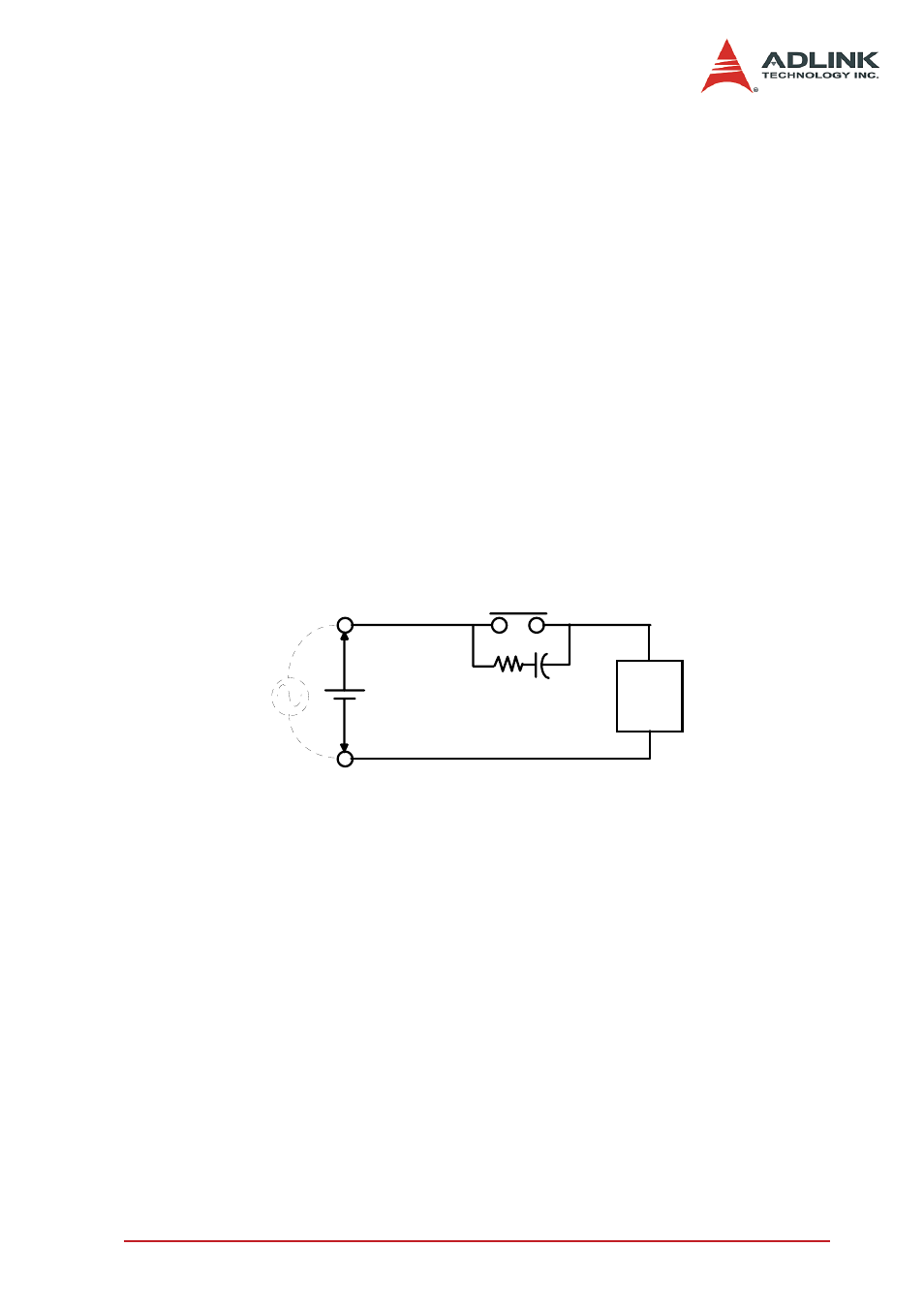
RC Circuit
This circuit is suitable for DC application. If the load is a timer,
leakage current flows through the RC circuit causing faulting oper-
ation.
The below circuit is suitable for both AC and DC applications. If
the load is a relay or solenoid, the release time lengthens. It’s
effective when connected to both contacts if the power supply volt-
age is 24V or 48V and the voltage cross the load is 100 to 200V.
Device Selection:
As a guide in selecting R and C,
Z
R : 0.5 to 1
Ω
per 1V contact voltage
Z
C : 0.5 to 1
μ
F per 1A contact current
Values vary depending on the properties of the capacity C acts to
suppress the discharge the moment the contacts open. Resistor R
acts to limit the current when the power is turned on the next time.
Contact
Inductive
Load
R C