Daq timing signals, Table 4-6: user-controllable timing signals and, Functionalities – ADLINK DAQe-2214 User Manual
Page 83
Operation Theory
71
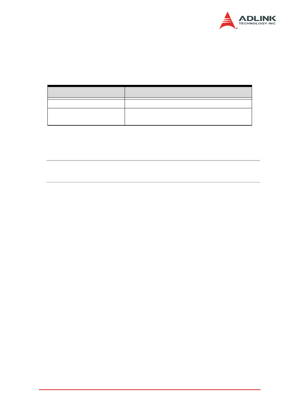
You can utilize the flexible timing signals through our software
drivers, then simply and correctly connect the signals with the
DAQ-/DAQe-2213/2214 card. Here is the summary of the DAQ
timing signals and the corresponding functionalities for DAQ-/
DAQe-2213/2214 card.
DAQ Timing Signals
NOTES
Refer to section 4.1 for the internal timing signal defini-
tion.
1. TIMEBASE provides the TIMEBASE for all DAQ opera-
tions which could be from an internal 40 MHz oscillator,
EXTTIMEBASE from I/O connector or the
SSI_TIMEBASE. Note that the frequency range of the
EXTTIMEBASE is 1 MHz to 40 MHz, and the EXTTIME-
BASE must be TTL-compatible.
2. AD_TRIG is the trigger signal for the A/D operation and
may come from external digital trigger, analog trigger,
internal software trigger, and SSI_AD_TRIG. Refer to
section 4.5 for detailed description.
3. SCAN_START is the signal to start a scan that would
bring the following ADCONV signals for AD conversion
and may come from the internal SI_counter, AFI[0] and
SSI_AD_START. This signal is synchronous to the
TIMEBASE. Note that the AFI[0] should be TTL-compat-
ible and the minimum pulse width should be the pulse
width of the TIMEBASE to guarantee correct functional-
ities.
4. ADCONV is the conversion signal to initiate a single con-
version and may be derived from internal counter, AFI[0]
or SSI_ADCONV. Note that this signal is edge-sensitive.
Timing signal category
Corresponding functionality
SSI/PXI signals
Multiple cards synchronization
AFI signals
Control DAQ-/DAQe-2213/2214 by external
timing signals
Table 4-6: User-controllable Timing Signals and Functionalities