5 isolated digital output (usb-7230 only), Isolated digital output (usb-7230 only), Figure 3-10 – ADLINK USB-7250 User Manual
Page 44: Digital filter example, 34 operations, Figure 3-10: digital filter example
34
Operations
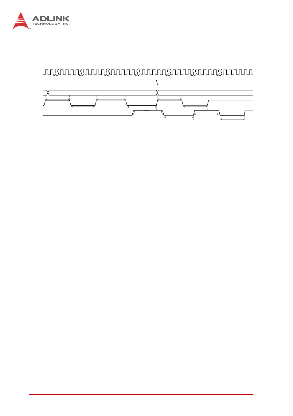
nals is 180 ns when filter is disabled, definitely, the last two states
are recognized.
Figure 3-10: Digital Filter Example
To reject a signal deviating from a state for the specified period of
time (minimum pulse width), the filter stage must be set to agree
with: 20.83 ns × filter stage < minimum pulse Width (ns).
3.5 Isolated Digital Output (USB-7230 only)
As shown, when isolated digital output is ON, sink current is con-
ducted through the power MOSFET, and when OFF, no current
flows through the power MOSFET. When the load is of an “induc-
tance nature” such as a relay, coil or motor, the VDD pin must be
connected to an external power source, in order for the flywheel
diode to form a current-release closed loop, protecting the power
MOSFET from high reverse voltage generated by the inductance
load when the output is switched. The DO output status is saved in
the USB microcontroller and can be read back if necessary. The
USB-7230 also features programmable power-up output sta-
tus,allowing output in a known state when powered on. When the
module is powered off (ejected from the USB port), all digital out-
put reverts to OFF.
CLK
filter
enable
filter
stage
filter_out
000A
filter_in
Pulse Width = 180 ns
1
2
9
1
2
8
2
8
9
1
8
9
10
1
2
8
9
10
Pulse Width = 210 ns
1
2
8
9
1
2
8
9
1
2
Pulse Width = 180 ns
Pulse Width = 210 ns
Pulse Width = 210 ns
Pulse Width = 210 ns
Pulse Width = 180 ns
Pulse Width = 180 ns
Pulse Width = 180 ns
XXXX
Pulse Width = 180 ns