3 optical isolated frequency/event counter, Optical isolated frequency/event counter, Figure 3-6 – ADLINK USB-7250 User Manual
Page 41: Cos example, Figure 3-7
Operations
31
USB-7230/7250
Figure 3-6: COS Example
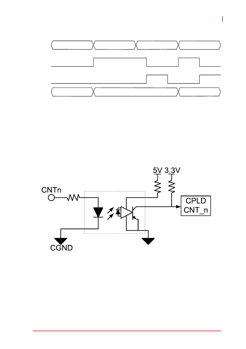
3.3 Optical Isolated Frequency/Event Counter
Calculates the number of rising or falling edges occurring on the
input channel, with counter width of 32 bits counting up from 0.
The polarity (rising or falling edge) of valid events is software con-
figurable.
Figure 3-7: USB-7230/7250 Optical Isolated Frequency/Event Counter
The frequency counter base clock is 48MHz. The frequency coun-
ter calculates base clocks occurring within a period (rising edge to
rising edge or falling edge to falling edge) of the repetitive input
signal, which is then converted to frequency value. Counter polar-
ity can be adjusted to rising edge active or falling edge active.
The following example shows frequency measurement of a 1 MHz
signal by counter0 with rising-edge polarity and 500 kHz signal by
DI
(all channels
enable)
Interrupt
Request
COS
Latch
register
0028
0029
FFFF
0028
FFFF
Interrupt
Clear
0027
XXXX
PHOTO COUPLER
n=0,1