4 digital filtering, Digital filtering, Figure 3-9 – ADLINK USB-7250 User Manual
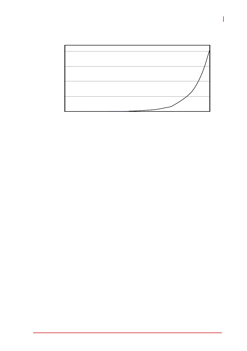
Page 43: Frequency counter error
Operations
33
USB-7230/7250
Figure 3-9: Frequency Counter Error %
3.4 Digital Filtering
Filters unexpected glitch signals from the input channels. By
default, when enabled, the input channel ignores signal changes
from one state to another when not remaining in the state for a
pre-defined period. The digital filter function is applied on all DI
channels and counters, with the default setting disabled. When
enabled by software,it is necessary to configure the minimum
pulse-width value. This value represents the minimum period of
time guaranteed to pass through the filter when the signal
changes. The digital filter uses an internal 16-bit counter to define
the specified filter value. Data is sampled by a 48 MHz base clock,
with minimum pulse-width value a multiple of 20.83 ns and multi-
ple number from 1 to 65535, representing the minimum
pulse-width from 20.83 ns to 1.365 ms.
In an examplary digital filter operation, as shown, data is sampled
by a 48 MHz base clock, and filter stage is 10, such that minimum
pulse width value is 208.3 ns. The pulse width of the first two sig-
nals is 180 ns, shorter than the specified filter value 208.3 ns.
Accordingly, the first two pulses are ignored, and the next two sig-
nals, with pulse width of 230 ns (longer than the specified filter
value 208.3 ns) are recognized. When pulse width of last two sig-
10000
100000
1000000
1000
100
2
1.5
1
.5
Frequency (Hz)
Error
(%)