1 isolated digital input, Isolated digital input, Figure 3-2 – ADLINK USB-7250 User Manual
Page 38: Usb-7250 functional block diagram
28
Operations
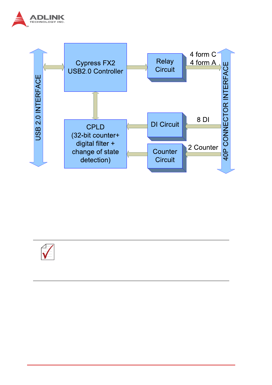
Figure 3-2: USB-7250 Functional Block Diagram
3.1 Isolated Digital Input
The USB-7230/7250 support 16 or 8 opto-isolated input chan-
nels,as follows, with digital input first routed through a photo-cou-
pler (PC3H4), and normal input voltage range for high state from 5
to 24V.
NOTE:
NOTE:
For USB-7230, all digital inputs share the same common junc-
tion (COM), with connections either common power or com-
mon ground, and with USB-7250, each input channel has an
individual differential input pair, preventing connections from
being polarity sensitive, irrespective of the connected voltage.
This manual is related to the following products: