13 general purpose i/o (gpio1), 1 gpio address select (jp3), 14 power connector (pwr1, pwr2) – Acrosser AR-B1673 User Manual
Page 16
AR-B1673 User’s Guide
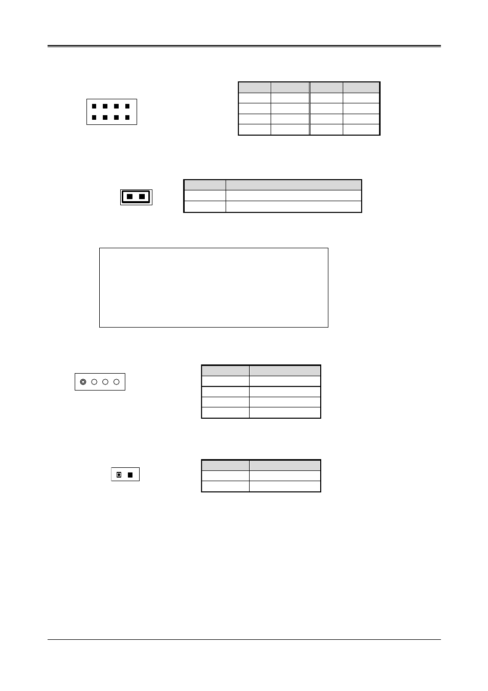
3.13 GENERAL PURPOSE I/O (GPIO1)
Pin
Signal
Pin
Signal
1 GPI0
2 GPO0
3 GPI1
4 GPO1
5 GPI2
6 GPO2
7 GPI3
8 GPO3
7 1
8 2
3.13.1 GPIO Address Select (JP3)
JP3
ADDRESS
ON 215H
(Factory
Preset)
OFF 77H
JP3
Users could test GPIO function under ‘Debug’ program as follow:
C:>debug
O 215 01H
Generally, the GPIO2 Pin2 will be High Level, others output pin
are Low Level.
I 215
FC
Generally, suppose that GPIO1’s Pin1 and Pin3 are High Level
then will show “FC”
3.14 POWER CONNECTOR (PWR1, PWR2)
PIN
Signal
1
+12V
2 GND
3 GND
4 VCC
(+5V)
1 4
(PWR1)
The PWR1 is a 4-pin power connector. It’s the standard connectors on all Acrosser boards.
PIN
Signal
1
-12V
2 -5V
1 2
(PWR2)
16
See also other documents in the category Acrosser Computer Accessories:
- AR-N6000 (28 pages)
- AND-D525N2 (38 pages)
- AND-D525N2 (30 pages)
- ANR-IB75N1/A/B (76 pages)
- ANR-IB75N1/A/B (60 pages)
- ANR-IH61N1/A/B (73 pages)
- ANR-IH61N1/A/B (57 pages)
- AR-R6000 (22 pages)
- AR-R6000 (32 pages)
- AR-ES0631ET (11 pages)
- AR-ES0631ET (15 pages)
- AR-R5800 (40 pages)
- AR-R5800 (58 pages)
- AR-R5800A (40 pages)
- AR-R5800 (40 pages)
- AR-R5800 (58 pages)
- AR-R5800 (58 pages)
- AR-N8601 (10 pages)
- AR-N8601 (31 pages)
- AR-R5700 (13 pages)
- AR-R6006 (24 pages)
- AR-R6006 (35 pages)
- AR-R6006 (24 pages)
- AR-R6006 (35 pages)
- AR-R8601E16 (8 pages)
- AR-N8601FL (37 pages)
- AR-N5205A (13 pages)
- AR-R5205FL (12 pages)
- AR-R5500 (10 pages)
- AR-B1550 (32 pages)
- AR-B1550 (32 pages)
- AR-B1550 (32 pages)
- AR-B1550 (37 pages)
- AR-B1551 (34 pages)
- AR-B1551 (37 pages)
- AR-B1551 (37 pages)
- AR-B1551 (37 pages)
- AR-B1551 (37 pages)
- AR-B1551 (37 pages)
- AR-B1551 (37 pages)
- AR-B1893 (35 pages)
- AR-B1893 (35 pages)
- AR-B1841 (36 pages)
- AR-B104D (27 pages)
- AR-B104D (7 pages)