Attaching the pulley guards – Delta 28-276 User Manual
Page 14
14 - English
THE BAND SAW IS VERY HEAVY. Use a helper when you attach the saw to the stand.
1. Place the band saw on top of the stand as shown in
Fig. 17.
NOTE: Confirm that the pulley is on the same side
of the stand as the pulley guard.
2. Align the four holes in the saw with the four holes in
the top of the stand.
3. Place an M8 lockwasher and a M8 flat washer on a
hex head screw (M8x1.25x40mm). Insert the screw
through one of the holes (A) in the saw and the
stand.
4. Thread a hex nut (M8x1.25) on the screw and tighten
securely.
5. Repeat this process for the other hole (A).
6. Attach the belt to the saw and motor pulley. See the
section "ATTACHING BELT TO SAW AND MOTOR
PULLEY".
7. Repeat
STEPS 3 AND 4 for the two remaining holes (B) Fig. 17 (one of which is shown).
ATTACHING THE SAW TO THE STAND
ATTACHING THE BELT TO THE SAW AND MOTOR PULLEY
1. Place the belt over the saw pulley (A) Fig. 18.
NOTE: The model 28-276 has a one-step pulley. The
model 28-206 has a two-step pulley (Fig. 18).
2. Lift the motor and place the other end of the belt
around the motor pulley (B) Fig. 18. The weight of
the motor will provide the correct belt tension.
Operate the machine ONLY with all the
guards in place and secure.
3. Check the alignment of the motor and saw pulley.
4. Loosen the four bolts (C) Fig. 12 that hold the motor
bracket to the motor mounting plate, and adjust the
position of the motor until the motor pulley and saw
pulley are aligned.
5. Tighten the four bolts that were loosened in STEP 4.
6. Turn bolt (C) Fig. 18, clockwise, until the dampening cap contacts the motor.
7. Back the bolt (C) Fig. 18 out approximately 1/4" and tighten the nut (D) against the top of the stand to hold bolt
(C) in place.
NOTE: Do not use the bolt and dampening washer to tension the belt. These two parts prevent the motor from
rising excessively when the motor starts.
A
B
C
D
A
B
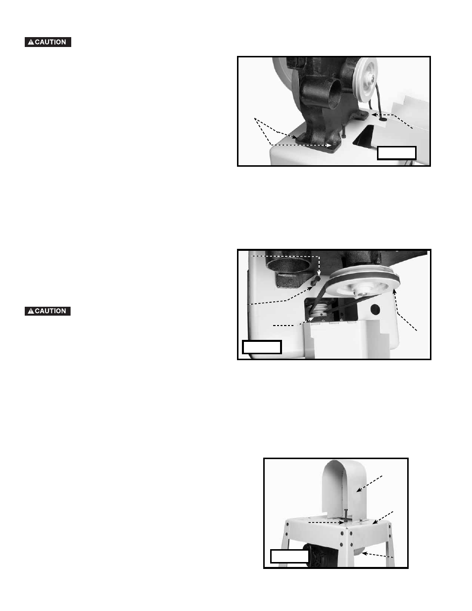
1. Insert the two threaded studs on the lower pulley
guard (C) Fig 18A through the two holes in the top
of the stand (B).
2. Align the two holes in the upper pulley guard (D)
Fig. 18A with the two threaded studs on the lower
pulley guard (C). Place the upper pulley guard on the
studs of the lower pulley guard.
3. Thread a hex flange nut (M8x1.25) on each of the
studs and tighten securely.
A
C
B
D
ATTACHING THE PULLEY GUARDS
NOTE: The illustration in Fig. 18A shows the stand
without the band saw for clarity.
Fig. 17
Fig. 18
Fig. 18A