Dialogic Integrated Media Gateways IMG 1010 User Manual
Page 5
Installing a Dialogic
®
1010 VoIP or Media Module
Dialogic Corporation
Part # 07-8740-01
Page 5 of 6
4.
Re-insert Dialogic
®
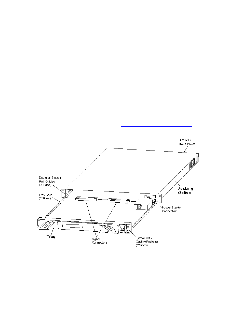
IMG 1010 Motherboard Tray. Align the rail on each side of the tray with the
guides on the inside of the docking station.
5.
Verify the ejectors are in the up position.
6.
Slide the tray in until the power connectors and signal connectors initially mate (the ejectors will
start to move down).
Cautions:
Do not force the tray if any resistance occurs when mating with the docking station. Using undue
force could damage the unit.
The guides only provide gross alignment to the power and signal connectors. The guide pins on the
main board and I/O card are self-aligning and provide alignment for the connectors.
The tray guides also act as the conduit for any Electrostatic Discharge (ESD) as the tray initially
mates with the docking station.
7.
When the tray is seated and the connectors are mated, push the ejectors down and tighten the
captive fasteners.
8.
Switch the power to ON (1) at rear of docking station.
9.
Configure Module. See Configuring Media or Configuring VoIP in the On-line Help Documentation
on the Dialogic Technical Support web site:
http://www.dialogic.com/manuals
Diagram 1 - Removing Dialogic
®
IMG 1010 Motherboard Tray