Specifications, Replacement parts, Technical service – Desa VSGF28NTE User Manual
Page 25: Service hints, Wiring diagram
www.desatech.com
113135-01A
25
SPECIFICATIONS
VSGF28NTE
VSGF28PTE
Btu (Low/High)
20,000/28,000
20,000/28,000
Type Gas
Natural Gas Only Propane/LP Gas Only
Ignition
Piezo
Piezo
Manifold Pressure
3.4" W.C.
7.9" W.C.
Inlet Gas Pressure (in. of water)
Maximum
10.5"
14"
Minimum
5"
11"
Shipping Weight
100 lbs.
100 lbs.
REPLACEMENT PARTS
Note:
Use only original replacement parts. This
will protect your warranty coverage for parts re-
placed under warranty.
PARTS UNDER WARRANTY
Contact authorized dealers of this product. If they
can’t supply original replacement part(s), call
DESA Heating Products’ Technical Service De-
partment at 1-866-672-6040.
When calling DESA Heating Products, have ready
• your name
• your address
• model and serial numbers of your fireplace
• how fireplace was malfunctioning
• type of gas used (propane/LP or natural gas)
• purchase date
Usually, we will ask you to return the part to the
factory.
PARTS NOT UNDER WARRANTY
Contact authorized dealers of this product. If they
can’t supply original replacement part(s), call
DESA Heating Products at 1-866-672-6040 for
referral information.
When calling DESA Heating Products, have ready
• model number of your fireplace
• the replacement part number
TECHNICAL SERVICE
You may have further questions about installation,
operation, or troubleshooting. If so, contact DESA
Heating Products’ Technical Service Department
at 1-866-672-6040. When calling, please have your
model and serial numbers of your heater ready.
You can also visit DESA Heating Products’ tech-
nical services web site at
www.desatech.com
.
SERVICE HINTS
When Gas Pressure Is Too Low
• pilot will not stay lit
• burners will have delayed ignition
• fireplace will not produce specified heat
• propane/LP gas supply might be low
You may feel your gas pressure is too low. If so,
contact your local propane/LP gas supplier.
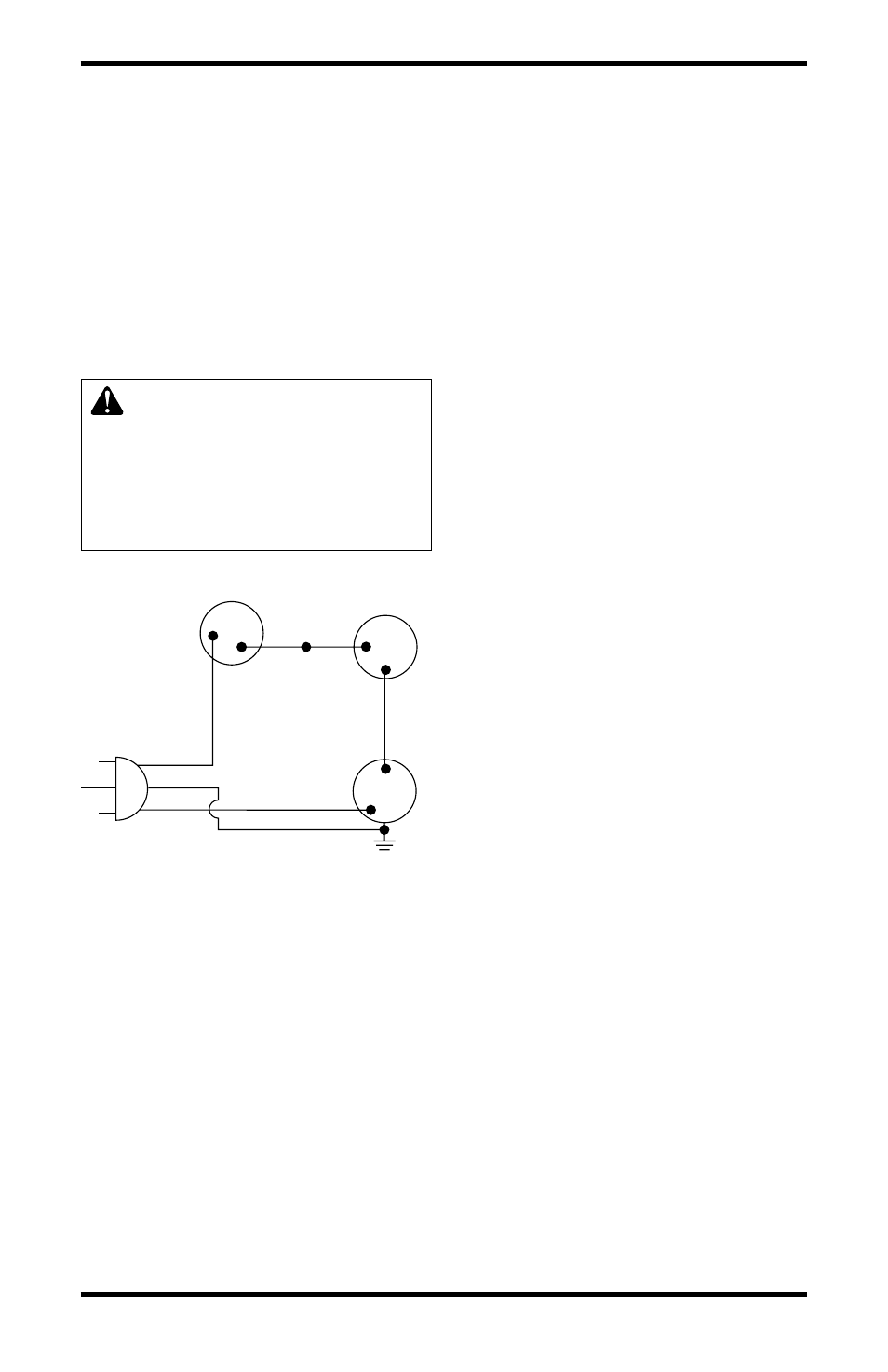
WIRING DIAGRAM
CAUTION: Label all wires
prior to disconnection when
servicing controls. Wiring errors
can cause improper and dan-
gerous operation. Verify proper
operation after servicing.
Red
Variable
Fan Switch
Fan Switch
(N.O.)
Green
White
On
110/115
V.A.C.
Blower
Motor
Black
Off
1
2
Black
Blue
Figure 36 - Blower Wiring Diagram for
Thermostat-Controlled Models