Part names and functions – Denon DN-X1100 User Manual
Page 6
Connections
Fader Star
t
ENGLISH
Specifications
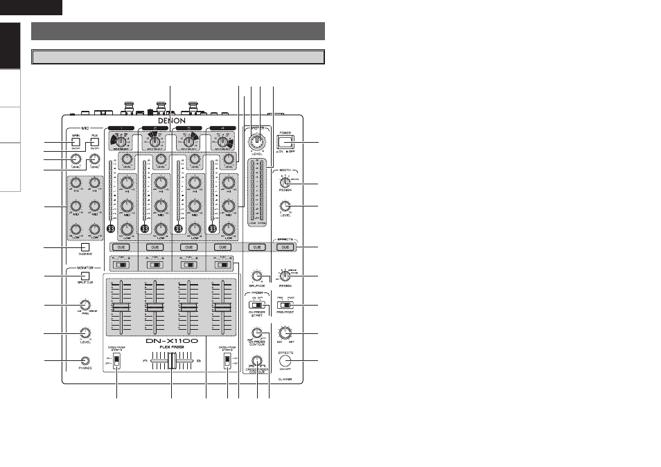
Top Panel
Part Names and Functions
q
w
e
r
t
y
u
i
o
Q0
Q1
Q2
Q3
Q1 Q4
Q5 Q6
Q9
W0
W1
W2
W3
W4
W5
W6
W7
W8
W9
E1
E0
E2
Q7
Q8
q
MAIN MIC ON/OFF button
When the button is lit, Main Mic signal is
transferred to output section, otherwise Main
Mic input is muted.
w
AUX MIC ON/OFF button
When the button is lit, Aux Mic signal is
transferred to output section, otherwise Aux
Mic input is muted.
e
MAIN MIC LEVEL control
Adjusts the level of the Main Mic input.
r
AUX MIC LEVEL control
Adjusts the level of the Aux Mic input.
t
MIC EQ controls
Contour the frequency response of the Mic
input –12 dB to +12 dB.
HI
Adjusts high-tone Mic sound –12 dB to +12 dB.
At the center position, sound is flat.
MID
Adjusts mid-tone Mic sound –12 dB to +12 dB.
At the center position, sound is flat.
LOW
Adjusts low-tone Mic sound –12 dB to +12 dB.
At the center position, sound is flat.
y
DUCKING ON/OFF button
• Use this to switch the Talk Over function ON and
OFF. (ON/OFF is cyclic)
• When the button is lit, level of signals except
Mics is attenuated.
• The DUCKING attenuation level adjusts. See
below rear panel o (vpage 4).
u
SPLIT CUE button
• In the STEREO mode, this button feeds STEREO
Program (CUE MASTER) and Cue to both
earcups, in the SPLIT CUE (MONO) mode, the
headphone circuit provides MONO Cue to the
left ear and MONO Program (MASTER) to the
right.
• In the STEREO mode, the meter indicates the
stereo level in the LEFT and RIGHT Master
Outputs. In the SPLIT CUE (MONO) mode,
mono Cue level is displayed on the Left meter
and mono Program (CUE MASTER) level is
displayed on the Right meter.
• In the SPLIT CUE (MONO) mode, the button is
lit.
i
HEADPHONE PAN control
Serves two purposes∙∙∙ In the STEREO mode
it changes the relative levels of the Cue and
Program mixed together in both ear cups. In the
MONO mode it changes the balance between
the Mono Cue in the left ear cup and the Mono
Program in the right.
o
HEADPHONE level control
Adjusts the volume for the headphones.
Q0
HEADPHONE output jack
Accepts 1/4” stereo headphone plugs.
Q1
CROSSFADER START A, B switches
Use this to switch the Crossfader Start function
ON and OFF.
Q2
CROSSFADER
Controls the relative output level from the
summed A and B Mixes. When the fader is
at its far left, only the A Mix is heard from the
Outputs. As the fader is moved toward the
right, the amount of B Mix is increased and the
amount of A Mix is decreased. When the fader
is centered, equal amounts of A and B Mixes are
routed to the Outputs. Fully right is all B Mix at
the Outputs.
• LINE 2, 4, 6, 8 FADER output terminals
(Rear Panel i (vpage 4))
ø 3.5 mm stereo mini terminal
Others should not be affected a terminal short-
circuit.
Q3
Source input fader (Ch. fader)
Controls the level of the selected Input.
Q4
CROSSFADER ASSIGN switches
A, B:
The channel source is assigned to A or B of the
Crossfader.
THRU:
Select when you don’t assign the channel source
into the Crossfader.
Getting Started