Step 1 – Directed Electronics 335912 359D User Manual
Page 13
10
© 2 0 0 2 d i r e c t e d e l e c t r o n i c s , i n c .
step 1
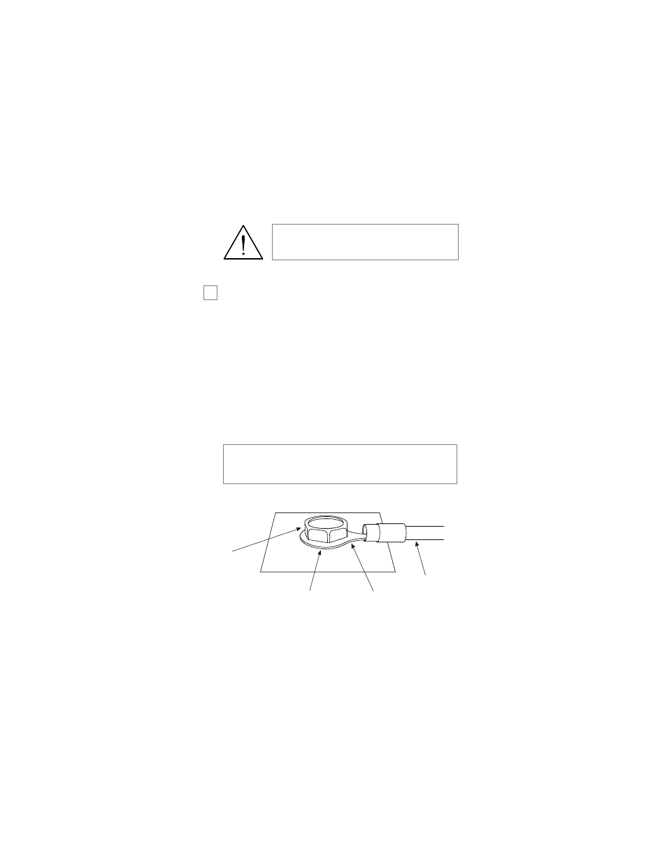
Ground Wire
The BLACK wire on the main 8-pin harness is ground. This
wire should be connected to a clean, paint-free area of metal in
the drivers kick panel area. First strip back a ¾-inch section of
the insulation off the BLACK wire and crimp a ring terminal
(not provided) to that wire. Locate a clean, paint-free metal
surface in the drivers kick panel. Using a self-tapping screw, drill
the screw with the ring terminal to the metal area. Once screwed
down, pull on the wire to ensure a good connection.
SELF-TAPPING
BOLT OR SCREW
RING
CONNECTOR
GROUND
WIRE
NOTE: REMOVE ANY PAINT
BELOW RING CONNECTOR
DIA-591
note: More problems are attributed to poor ground con-
nections than any other cause. Take extra care to ensure
the ground is clean and secure.
➜
warning! Verify that the vehicle is set to
park and that the parking brake is set
before beginning installation.