Block diagram xr-3000, Ashly audio inc, R ir ir r – Ashly 24db Per Octave Electronic Crossover XR-2000 User Manual
Page 2: Specifications, Since 1972
Attention! The text in this document has been recognized automatically. To view the original document, you can use the "Original mode".
Specifications
CONTROLS
Input Level;
Response Control:
Output Level:
Input Impedance:
Maximum Input Level:
Maximum Output Level:
Frequency Response:
Distortion:
Siew Rate:
Hum and Noise:
Power Requirements:
Size:
Shipping Weight:
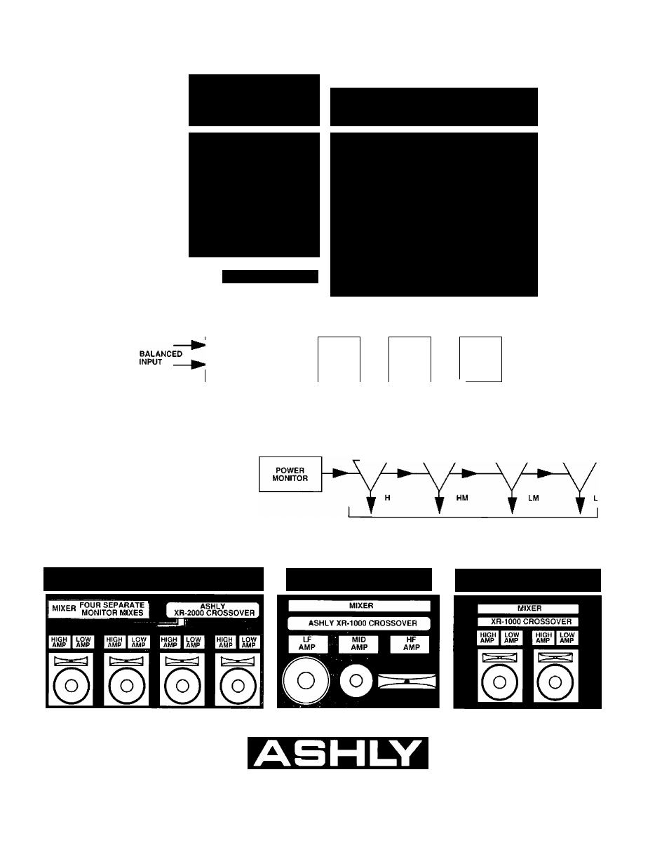
Block Diagram XR-3000
oo - +6dB
1.5dB- 12dB
- ■»■20dB
tOkii baianced bridging
•!-26dBm
+20dBm
±.5dB 20Hz-20kHz
<.05% THD
6V/|iS
•90dBv
120VAC, 50-60HZ, 5W
XR-1000, XR-3000:19"L x 1.75"H x 6"D
XR-2000, XR-4000: 19"L x 3.5"H x 6’’D
XR’IOOO, XR-3000: 8 ibs.
XR-2000, XR-4000: 10 ibs.
FILTERS
INPUT
GAIN
^
FROM
-ROM FROM OUTPUT
Ashly also manufactures a
complete and comprehen
sive line of 12dB per Octave
Electronic Crossovers as
well as Power Amplifiers,
Compressor/Limiters, Noise
Gates, Graphic and
Parametric Equalizers, and
Preamps. Please call or write
for information on any of
these Ashly Products.
Typical Hookup Of XR-2000 in 4-Channel, Two-
Way Operation (Multiple-Mix Stage Monitors)
INPUT FILTERS STAGES
HM
LM
PEAK INDICATOR
r ir ir r
Typical Hookup Of XR-1000 in
Mono, Three-Way Operation
OUTPUT STAGES
Typical Hookup Of XR-1000 in
Stereo, Two-Way Operation
Ashly Audio Inc.
Since 1972
© 1990 Ashly Audio