The fet-1000m (top) features xlr and 1/4" inputs, Ashly, Specifications – Ashly FET-1000C User Manual
Page 2: Since 1972
Attention! The text in this document has been recognized automatically. To view the original document, you can use the "Original mode".
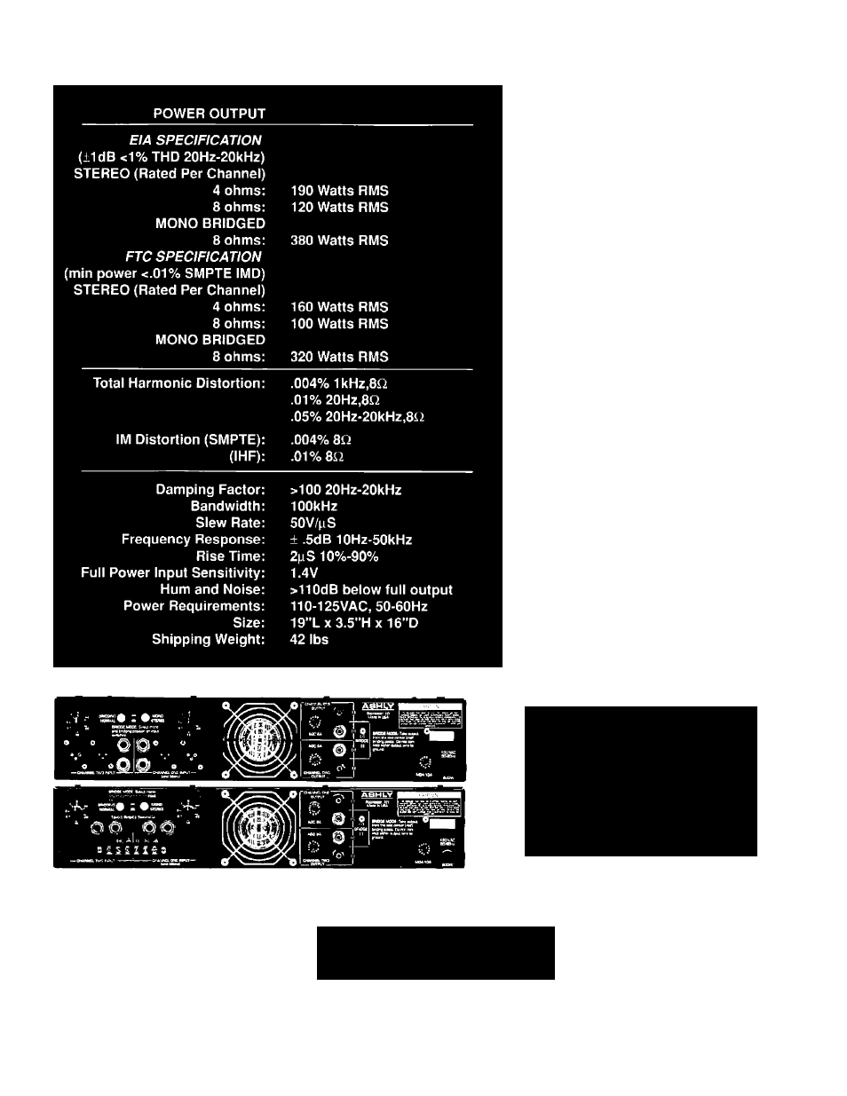
Specifications
Architect’s Specification
Ashly Model lOOOM
The power amplifier, being of two channels, shall deliver a
niinimiim power of 100 watts per channel Into 8 ohm loads
or 160 watts per channel Into 4 ohm loads with both chan
nels operating. When switched Into bridged mono mode. It
shall deliver at least 200 watts into a 16 ohm load or 320
watts Into an 8 ohm load. The aniplllicr shall be immune to
damage from shorted, open, or mismatched loads. Tlie
amplifier shall have a gain of 26dB ± ,5dB per channel and
an Input sensiUvily of 1.4 Volts ± 2% for full rated output.
Frequency response shall be lOHz to 20kHz ± .5dB. It shall
be stable Into any load Including pure capacitors and
indiietors. Hum and noise shall be at least llOdB below
full output and SMPTE intermodulation dislortion shall be
less Uian .01% at full output. The ampliller shall have rear
panel switching for mono and bridging modes and rear
mounted level controls. Tlie inputs shall be Ijalanced bridg
Ing type with male and female XLH type connectors as well
as 1/4 " phone Jacks. A three-color LED lype Indicator shall
be employed to show the power le\'el of each channel and
self contained forced air cooling shall be used. The power
outpiil devices shall be of the Lateral MOS-FET type. Tlie
aniplltler shall weigh 321b. net and mount in a standard 19
Inch rack using two spaces 13,5' high|. The power require
ment shall be 110-125VAC, 50-601 iz,
The power amplifier shall be an Ashly FEf- lOOOM.
Ashfy Model lOOOC
llic power amplifier, being of two channels, shall deliver a
minimum power of 100 watts per channel into 8 ohm loads
or 160 watts per channel Into 4 ohm loads with both chan
nels operating. When switched Into bridged mono mode. It
shall deliver at least 200 watts into a 16 ohm load or 320
walls Into an 8 ohm load. Tlie amplifier shall be immune to
damage from shorted, open, or mismatched loads. The
ampliner shall have a gain of 26dB ± .5dB per channel and
an Input sensitivity of 1.4 Volts ± 2% for full rated output.
Frequency response shall be lOHz to 20kllz ± .5dB. It shall
be stable Into any load including pure capacitors and
Inductors, Hum and noise shall he at least llOdB below
full ou [put and SMITE infermodiilatiou dislortion shall be
less than .01% at full output. The ampliller shall have rear
panel srvitchlng for mono and bridging modes and rear
mounted level controls. The inputs shall utilize 1 /4" phone
jacks as well as termlnal/barrier input strips. Self con
tained forced air cooling shall be used. The power oiilpul
devices shall be of the Lateral MOS-FET type. The amplifier
shall weigh 321b. net and mount in a standard 19 Incli rack
using two spaces (3.5" high]. The powci- requirement shall
be 110-125VAC. 50-60HZ.
The power amplifier shall be an Ashly FBT- lOOOC.
To provide maximum flexibility,
Ashly offers two variations in our
FET Power Amplifiers:
The FET-1000M (top) features XLR
and 1/4" inputs.
The FET-1000C (bottom) utilizes
Barrier Strips and 1/4” inputs.
ASHLY
Since 1972
© 1990 Ashiv Audio