Ashly Power Amplifiers FET-200 User Manual
Page 6
Attention! The text in this document has been recognized automatically. To view the original document, you can use the "Original mode".
INPUT AND OUTPUT CONNECTIONS
STEREO OPERATION
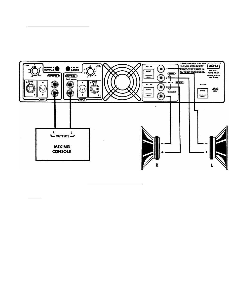
Connections for stereo operation are shown in figure 4 below.
Figure 4 Stereo Operation
INPUTS
The input of Asnly amplifiers is a balanced bridging type, with an input
impedance of 10k ohms. Use of the balanced input provides superior hum and
noise rejection while eliminating ground loops. The input may also be used in
a single-ended, unbalanced mode by simply using unbalanced input connectors.
Each channel provides a choice of either 1/4” jacks or XLR input connectors.
All four connectors are in parallel. Since only one of the four connectors is
used as an input at any one time, the others may be used to jumper other
amplifiers to the same source.
Signal connections are as follows:
The (+) or in-phase connection is on the tip of the 1/4" stereo phone jacks,
and is on pin 3 of the XLR connectors. The (-) or out-of-phase connection is
on the ring of the phone jacks and on pin 2 of the XLR's. Chassis ground and
shield is on the sleeve of the 1/4" jacks and pin 1 of the XLR's.