Typical, Applications, Crossover input option – Ashly MOS-FET POWER AMPLIFIERS CFT-SERIES User Manual
Page 5: Mic/ljne mixer input option, X xi, Stereo operation, Meters
Attention! The text in this document has been recognized automatically. To view the original document, you can use the "Original mode".
CROSSOVER INPUT OPTION
The crossover input option provides fixed-froquency 24 dB/octave high-pass and
low pass filtei^ allowing the two amplifier channels to operate bi-amped, full range with low
out both channels low out, or bridged low out. Auxilliary low and high outputs are available
for connecting additional amplifiers, included widi the crossover input option are single in
line package (SIP) resistor networks which allow preselection between stimdard crossover
frequencies of 160Hz, 500Hz, and 1,2KHz. 360° of phase control is provided for proper
acoustical alignment of high and low frequency drivers. Constant Directivity Horn EQ is
provided for both small and large hom designs. A 3rd-order 20 Hz high-pass filter is
included on the low frequency crossover output to remove inaudible subsonic signals.
MIC/LJNE MIXER INPUT OPTION
The mixer input option provides four high-impedance line inputs and two
balanced low-impedance microphone inputs, each with its own level control. A
switchable 200 Hz high-pass filter is provided on the mic inputs to reduce unwanted
low frequency noise. An interna! jumper allows selection of 15 Volt phantom power
applied to the mic inputs for use with condenser mics. The option has a master level
control and selectable stereo, mono and bridging modes, insert Points are available
for patching external processing into the left and right channels.
Qî.S
Limiter
Thresbotd Umit
(dB) I
Stereo
Mono
Norm
Bridge
Ch.1
Umteer , ,
ThresMiJ wfTiït
ieJB} f
+18
) ( ; +13.
.as '■
■15
-N
'■ N
+3'^ V
+3Vj C-®
1
■6
■ Б
CL-2
POWERCAPD input Option
Stereo
limiter
4 f 6 //
Ч... ./ О 10
Limiter Leve!
tn/Out
, ,
, , Ground
(+) И О
[-) [+М
X
X Xi
X
Channei Э
Chassis
Ground
14 4^6
O
^ 10 \
Levd Limiter
(пДЭиЕ
' Channel 1 (Mono)
Figure 7: Limiter Input Option
• • • • • • • • • • • • •
Ashly FTX/CFT Owners Manual
Page 8
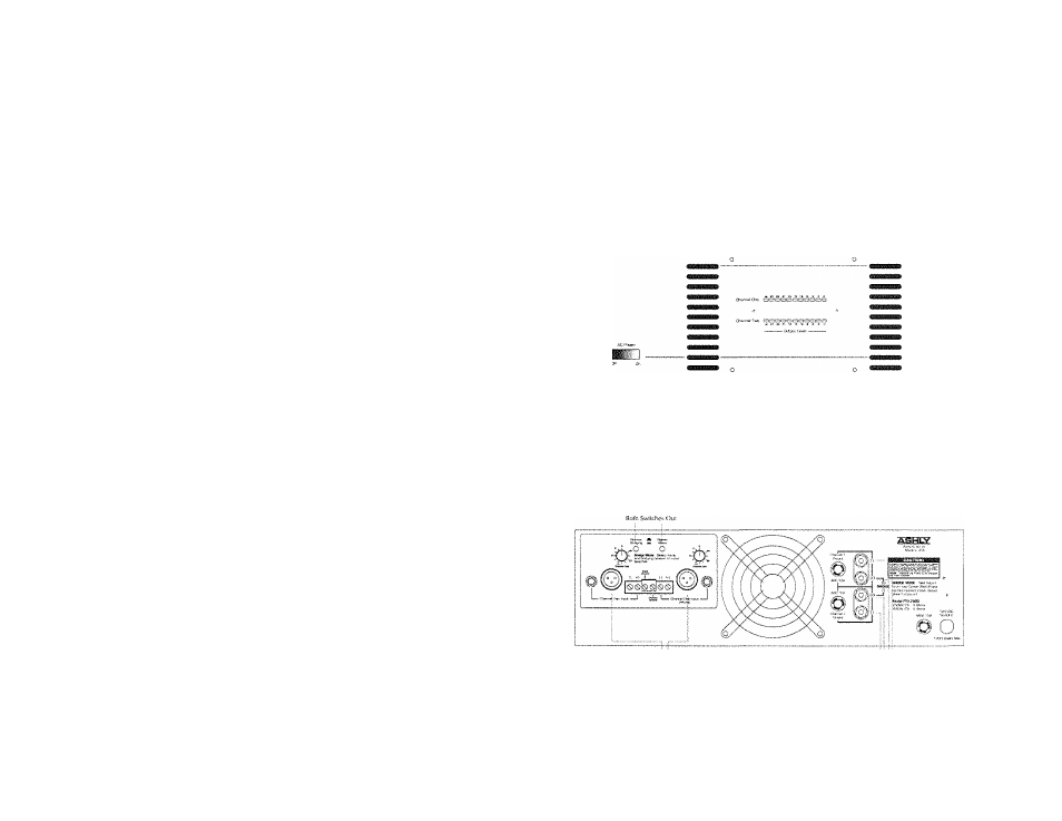
METERS
The FTX amplifiers are equipped with front panel meter displays which
respond to peak output voltage. An eleven-segment, three-color LED display
covers a 27 dB range. The green LED’s at the left end of the meter arrays indicate
a normal thermal status. In the event that the amplifier overheats, these LED’s will
turn off but the power switch will remain illuminated, indicating the thermal
protection status. When the heat sinks return to safe operating temperatures, the amp
will turn itself back on and illuminate the left-most green LED’s. In the event of a
blown speaker fuse, the meter display of the affected channel turns fully on. THIS
DOES NOT MEAN THERE IS DC AT THE OUTPUT!
о
о
figure 3: FTX~2000 Front Panel
TYPICAL
APPLICATIONS
STEREO OPERATION
lissitiâsg i t S
Figure 4: Operation in Normal Stereo Mode
• • • • • • • • • • • • • • • • • • • •
Ashly FTX/CFT Owners Manual
Page 5