Ashly SC88 User Manual
Page 2
Attention! The text in this document has been recognized automatically. To view the original document, you can use the "Original mode".
BIOCK DIAGRAM
OUTPUT STAGES
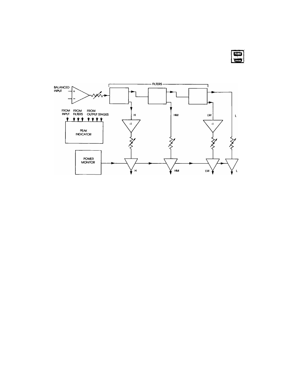
The SC-88 uses state-variable filter circuits to perform the frequency divisions. These filters provide
simultaneous low-pass and high-pass outputs. Three filters are cascaded for four-way operation.
Inverters are included on alternate outputs to keep everything in-phase. A “ Q " adjustment (called
rolloff) is included for adjustment of frequency response in the crossover region. This allows flat summing
and in-phase outputs.
The output stages have a wide range gain adjustment with a special feedback level control circuit to
maintain an optimum signal-to-noise ratio at any setting.
A special electronic power monitor for the output stages prevents turn-on transients without the use of
relays.
Both inputs and outputs can be used ds balanced or unbalanced and a peak overload circuit monitors
all critical points in the circuit to insure low-distortion operation.
SPECIFICATIONS:
Input gain;
Crossover frequencies:
Slope:
Rolloff:
Output gain:
Input impedance:
Output impedance:
Max. in-out level:
Frequency response:
Distortion:
Hum and Noise:
Power:
Shipping Weight:
- 0 0 - -MOdB
16HZ-800HZ, 160Hz-8kHz, 480Hz-24kHz
12dB/OCT.
1.5dB-12dB (crossover point depth)
- 0 0 - -h20dB
10k balanced bridging
50/^unbalanced-terminate with 600/Лог more
-F20dBV
±.5dB 20Hz-20kHz (within passband)
<.05% THD. -FIOdBV 20 Hz-20 kHz
-90dBV
120 VAC, 50-60Hz, 5W.
10 lbs