Securing the cables (hardware e), Attaching the starter rope (hardware c), Final assembly of mower – Bolens 112-413R352 User Manual
Page 6
Attention! The text in this document has been recognized automatically. To view the original document, you can use the "Original mode".
5.
Holding the control box near the left side of the
upper handle (control box must be inside the han
dle), hook the “Z” end of the brake cable into the
control handle from the outside to the inside. See
figures 3 and 4.
Place the control box on the upper handle just
below the end of the control handle as shown in
figure 4. Secure with hardware removed in step
one by placing hex lock nut into the indent on the
inside of the control box. Screw the truss machine
screw into the hex lock nut.
SECURING THE CABLES (Hardware E)
Secure the cables to the left side of the handle as fol
lows.
A
WARNING:
When
attaching
the
control
cables,
the
cables
must
be
routed
to
avoid
contact
with
all
sharp
edges
and
hot
surfaces
to
prevent
damage
to
the
cables,
which
will
render
the
controls
inoperative.
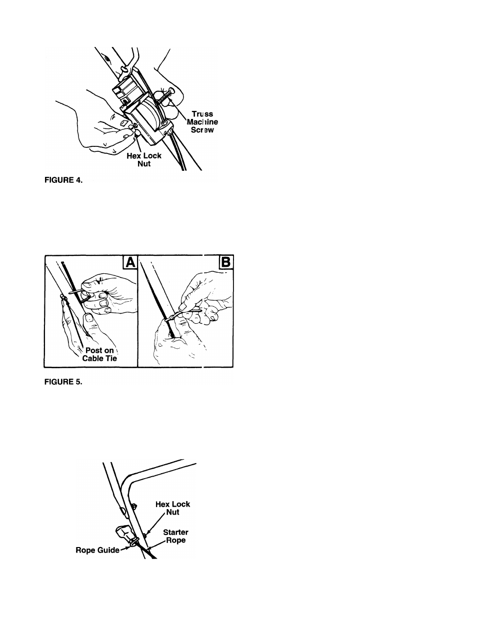
1.
Insert posts on cable ties into holes provided on
the lower handle. The holes may be either on the
— inside or outside of the handles. See figure 5A.
2.
Secure the cables with the cable ties, making cer
tain the cables do not contact the wheel. See fig
ure 5B. Trim excess ends of cable ties.
ATTACHING THE STARTER ROPE (Hardware C)
1.
The starter rope is inside the top of the engine.
Additional rope may be wound around the starter
handle. If so, unwind the rope from the handle.
2.
With
the
spark
plug
wire
disconnected
and
grounded, depress the blade control handle and
pull the rope out of the engine.
3.
Place the rope guide around the starter rope, so
the rope guide is positioned as shown (bends
downward slightly). Insert the rope guide through
the right side of the lower handle, and secure with
------ hex lock nut. See figure 6.
FIGURE 6.
FINAL ASSEMBLY OF MOWER
Make certain all nuts and bolts are tightened securely.