Specifications – Ashly SC77 User Manual
Page 2
Attention! The text in this document has been recognized automatically. To view the original document, you can use the "Original mode".
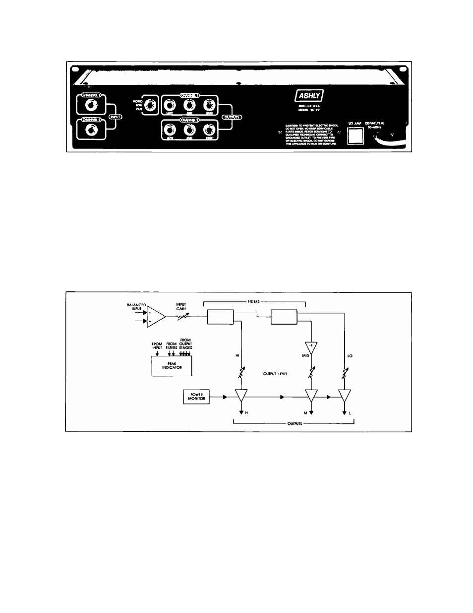
The SC-77 uses state variable filter circuits to perform
the frequency divisions. These filters provide simulta
neous low-pass and high-pass outputs. Twofiltersare
cascaded for three-way operation. Inverters are
Included on the mid outputs to keep everything in-
phase. A "Q" adjustment (called rolloff) is included
for adjustment of frequency response In the cross
over region. This allows flat summing and in-phase
outputs.
The output stages have a wide range gain adjust
ment with a speciai feedback level control circuit to
maintain an optimum signal-to-noise ratio at any
setting.
A special electronic power monitor for the output
stages prevents turn-on transients without the use of
relays.
Both inputs and outputs can be used as balanced
or unbalanced and a peak overload circuit monitors
all critical points in the circuit to insure low-distortion
operation.
SPECIFICATIONS:
CONTROLS
Input level
crossover frequencies
rolloff
(crossover point depth)
output level
INPUT IMPEDANCE
OUTPUT IMPEDANCE
MAX. IN-OUT LEVEL
- oo -
-I
lOdB
48Hz-2.4kHz 480Hz-24kHz
1.5d8-12dB
- oo - -120dB
10k n balanced bridging
50 il unbalanced - terminate
with 600 il or more.
Turn on transient protected.
>20dBm
FREQUENCY RESPONSE
DISTORTION
HUM AND NOISE
(all outputs)
POWER
SIZE
SHIPPING WEIGHT
j..5dB 20Hz-20kHz (within
passband)
< .05% THD, +10dBV
20Hz-20kHz
-90dBV
Input and all outputs unity
gain,
frequency
and
rolloff
at center rotation.
120 VAC. 50-60HZ, 5W
19"L X 31/2"H X 6"D
10 lbs.