Banery removal or installation, Jump starting, Tires – Bolens 1208 User Manual
Page 14: Drive belt removal and replacement
Attention! The text in this document has been recognized automatically. To view the original document, you can use the "Original mode".
BAnERY REMOVAL OR INSTALLATION
A
^ WARNING; When removing the battery,
follow this order of disassembly to prevent
the screwdriver from shorting against the
frame.
1. Remove the Negative cable.
2. Remove the Positive cable.
To install the battery:
1. Attach the Positive cable.
2. Attach the Negative cable.
JUMP STARTING
1. Attach the first jumper cable from the Positive ter
minal of the good battery to the Positive terminal
of the dead battery.
2. Attach the second jumper cable from the Negative
terminal of the good battery to the FRAME OF THE
UNIT WITH THE DEAD BATTERY.
A
WARNING: Failure to use this starting pro
cedure could cause sparking, and the gas
in either battery could explode.
TIRES
Recommended operating tire pressure is approximately
12 p.s.l. (check sidewall of lire for tire manufacturer’s
recommended pressure). Maximum tire pressure under
any circumstances is 30 p.s.i. Equal tire pressure
should be maintained on all tires.
When installing a tire to the rim, be certain rim is clean
and free of rust. Lubricate both the tire and rim
generously. Never inflate to over 30 p.s.i. to seat beads.
A
WARNING: Excessive pressure (over 30
p.s.i.) when seating beads may cause
tire/ilm assembly to burst with force suffi
cient to cause serious Injury.
DRIVE BELT REMOVAL AND REPLACEMENT
NOTE:
It is recommended that the entire instructions
on belt removal and replacement be read before chang
ing the belts.
1. Disconnect the spark plug wire and ground it
against the engine.
2. Remove the deck as described in the separate
deck manual.
3. Unhook the idler spring from the lawn tractor
frame. See figure 17. Loosen the bolt which
secures the belt keeper to the idler pulley.
Torque Rod
Bracket
Spring
Hooked
in Frame
FIGURE 17.
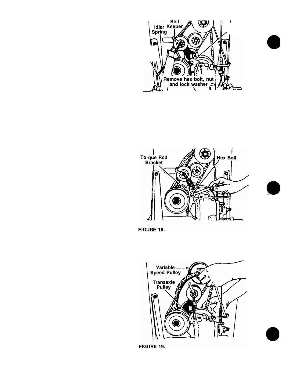
4. Remove the hex bolt, nut and lock washer at the
torque rod bracket and transaxle. See figure 16.
5. Remove the hex bolt which holds the torque rod
bracket to the torque rod, and remove bracket. See
figure 18.
6. Slip the "V”-belt off the variable speed pulley and
transaxie pulley. See figure 19.
14