Deck adjustment (models 1002 and 1208), Bude brake adjustment (model 800 only) – Bolens 1208 User Manual
Page 10
Attention! The text in this document has been recognized automatically. To view the original document, you can use the "Original mode".
/
'X-y
----
Front Deck
Lift Assembly
Connecting
Rod
Ferrule
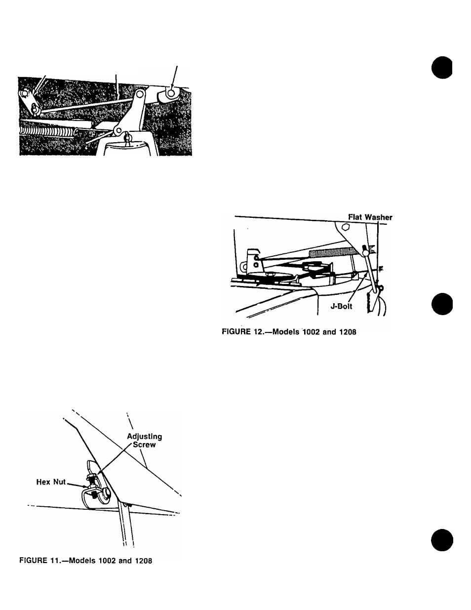
FIGURE 10.—Model 800
Front to Rear Adjustment
To obtain the best cut, the front of the deck should be
between 1/4" and 3/8" lower than the rear of the deck.
1
. Make the side to side adjustment as instructed
previously.
Measure the distance from the bottom edge of the
front and right rear of deck to the ground.
If the front is not between 1/4" and 3/8" lower than
the rear, remove the hairpin clips and flat washers
which secure the J-bolts to the front of the deck,
both right and left sides. See figure 12. Thread the
J-bolts into or out of the ferrules as necessary.
Reassemble J-bolts and recheck the adjustment.
Readjust as necessary. Secure with flat washers
and hairpin clips when adjustment is correct.
2
.
3.
4.
DECK ADJUSTMENT (Models 1002 and 1208)
Side to Side Leveling
NOTE:
Check tire pressure in aii four tires before level
ing the deck. Recommended tire pressure is 12 p.s.L
If an uneven cut is obtained, the deck may be leveled.
1. Raise the deck to its highest position.
2. With the unit on a hard, level surface, measure the
distance from the bottom edge of both the left rear
and right rear of deck to the ground.
3. If adjustment is needed, loosen the hex nut on the
adjusting screw, located under the right side of the
frame. See figure 11. Move the adjusting screw in
ward to lower the right side of the deck, or outward
to raise the right side of the deck.
4. Remeasure the deck as described in step 2, and
readjust if necessary. Tighten the hex nut to secure
the adjusting screw when the deck is level.
Hairpin Clip
BUDE BRAKE ADJUSTMENT (Model 800 Only)
A
WARNING: Make certain spark plug wire is
disconnected and grounded against the
engine while making this adjustment.
To adjust the blade brake, proceed as follows. See
figure 13.
1. Disconnect the brake cable from the lower inside
belt guard on the lawn tractor by removing the hair
pin cotter, flat washer and clevis pin.
Lower the deck to its lowest position. Place the
blade engagement lever in the disengaged
position.
Pull the brake cable back so there is no slack in
the cable. Do not put tension on the cable. Select
the hole in the lower inside belt guard which aligns
with the end of the cable. Move the end of the
brake cable forward to the next hole in the belt
guard (which will give a small amount of slack in
the cable), and reassemble.
2.
3.
10