Bolens 247.29773 User Manual
Page 8
Attention! The text in this document has been recognized automatically. To view the original document, you can use the "Original mode".
-v!2;" . ■
Do not use
these holes
•■ ' - ' M
^e these'
' ■* ’*■':’'»'J
FIGURE 9.
^1
?■
Throttle
Control V
Self Tapping
Screw
Screwdriver
FIGURE 10.
3. Clutch Control Rod.
The control rod comes from the factory with the
ferrule preadjusted. (See figure 11.) Place ferrule
in idler bracket. Secure with hair pin cotter.
NOTE
Figure 11 has the belt guard re
moved for clarity, it is not necessary
to remove for control rod assembly.
Place the shift lever (located on handle panel) in
neutral (N) position. Place other end of control
rod in shift lever and secure with hair pin cotter.
Idler Bracket.
..'■h'i
J
%
Fnrrula and
■it'irpi.n C:;ri2r
FIGURE 11.
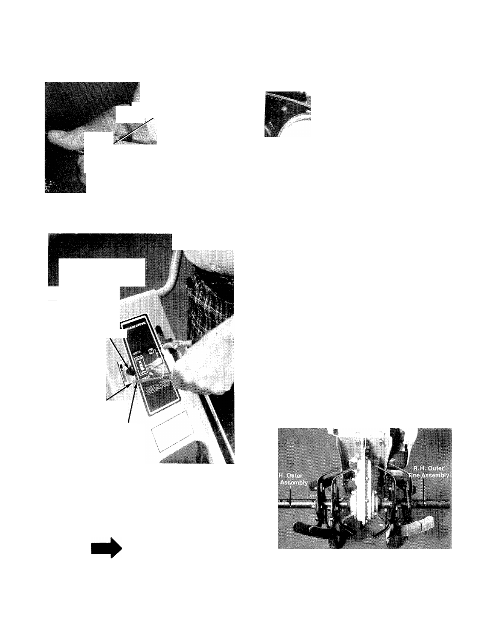
4. Tine Attachment.
a. The outer tines have been reversed on the
tine shaft for shipping purposes. See
figure 12.
Remove outer tines from the tine shaft and
reinstall with the tine hub facing inward as
illustrated in figure 13. Secure tines with
clevis pins (F) and hair pin cotters (I).
b. The inner tine assemblies have been
installed at the factory and in their correct
operating position and do not require
changing.
c. See tine adjustment for information on
changing width of tilling path, page 11.
FIGURE 12.