Assembly, Instructions, Assembly instructions – Bolens 247.29773 User Manual
Page 7
Attention! The text in this document has been recognized automatically. To view the original document, you can use the "Original mode".
ASSEMBLY
INSTRUCTIONS
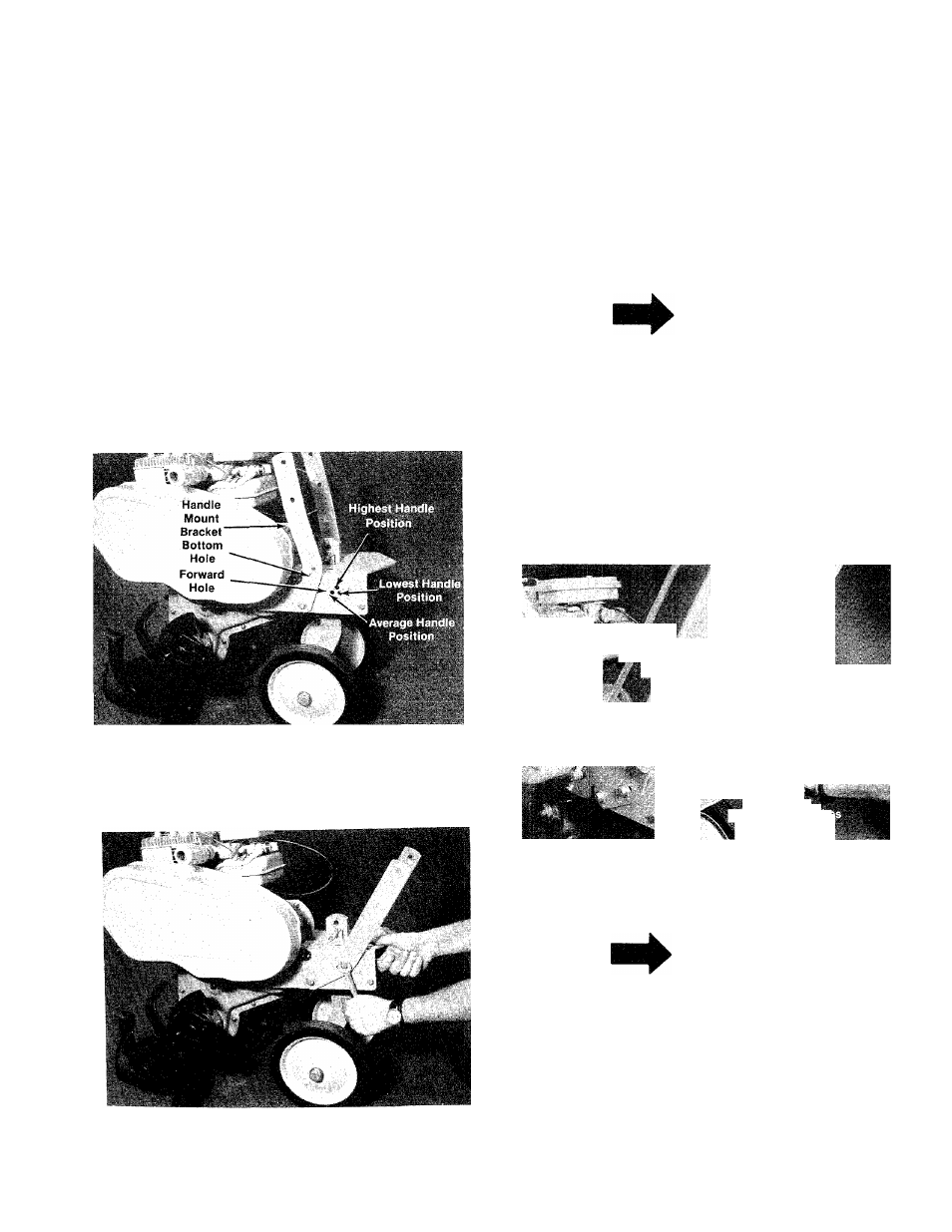
1. Handle Panel Attachment.
For shipping purposes, the handle mounting
brackets are pivoted forward. With a 9/16” wrench
loosen the hex bolt holding the handle mount
brackets. See figure 6.
Pull handle mount brackets back so that the
bottom hole in bracket lines up with forward hole
in chassis. See figure 5, 6 and 7.
Secure handle mount brackets with hex bolt (C),
lockwasher (D) and hex nut (E). See hardware,
page 4.
The handle panel is attached by sliding it down
over the handle brackets on the chassis and
installing four hex bolts in the lower holes of the
handle panel. Place bolts through the handle
panel; head to the outside. See figure 6.
NOTE
Do not tighten until all four bolts are
in place.
FIGURE 6.
Four hex bolts (H), lockwashers (D) and hex nuts
(G) will be found in the hardware pack. See figure
8
.
Handle Bracket
■
Handle Pans!
'
i
iV <
FIGURES.
2. Throttle Control Lever.
FIGURE 7.
NOTE
The throttle control has four holes in the
lever bracket. The holes on the outside
edge are to be used for mounting on this
unit. See figure 9.
Place throttle control lever up through the handle
panel and secure with two self tapping screws (B),
using a V
4
” flat screwdriver. See figure 10.