The controls – Black & Decker 3382 User Manual
Page 6
Attention! The text in this document has been recognized automatically. To view the original document, you can use the "Original mode".
4. Use the spanner wrench provided to loosen (counterclockwise) the blade
nut. Depress the spindle lock pin on the top of the gear case to hold the
spindle while you unscrew the nut.
5. Remove the blade and have it sharpened or replace it with a new one.
6. Reinstall the blade by reversing the steps above. Be sure blade teeth point
counterclockwise as shown in Figure 4.
7.
IMPORTANT:
Always check the fine depth adjustment when sharpening
or replacing the blade. Adjust if necessary (See "Controls" section).
The Controls
The heart of your plate joiner is the base/fence assembly. All of the controls
that let you make a variety of precision cuts are located on this assembly. Take
a few minutes to become familiar with the various controls.
ALWAYS TURN OFF AND DISCONNECT PLATE JOINER BEFORE MAKING
ANY ADJUSTMENTS.
ADJUSTABLE FENCE
The adjustable fence provides a sturdy, precise reference surface to deter
mine the point at which the slots for the biscuits will be cut. Its adjustable
height feature allows you to position biscuit slots as close as 3/16" (4.76mm)
and as distant as 1 -3/8" (35 mm) measured from the work piece surface to the
centerline of the blade (See Figure 6). The adjustable angle feature allows a
full range of settings from 0° to 90 as well as a reverse 45° bevel which allows
outside registration on miter joints. (See Applications section under Miter
Joints, Figure 26).
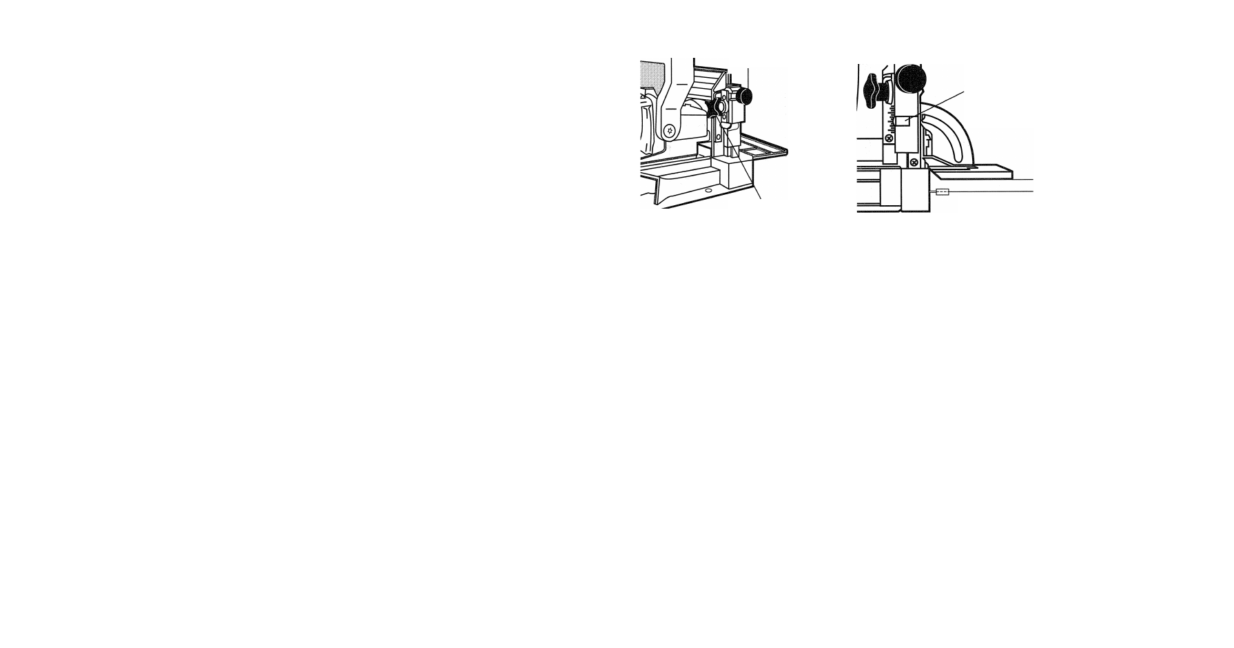
The height adjustment is accomplished by first loosening the lock knob on the
right side of the fence and then rotating the knurled adjustment knob until the
desired height is reached. (See Figure 5).
Tightening the lock knob will then automatically align the fence parallel to the
blade and lock it in position. The vertical scale and pointer located directly
Figure 5
ADJUSTMENT
KNOB
POINTER
POINTS TO
1.2” (12.7mm)
MARK
Figures
LOCK KNOB
1/2” (12.7mm)
CENTERLINE OF
BLADE
under the lock knob can be used to assist in setting this height. The scale
readings indicate distance from the blade centerline to the fence surface when
the fence is set at 90°. (See Figure 6). The fence angle can be set simply by
loosening the lock knob on the left side of the tool, aligning the protractor
scale with the pointer and tightening the lock knob.
PLUNGE DEPTH ADJUSTMENT
The depth of cut can be set to match the dimensions of the particular size bis-
cuit you will be using. The numbers on the depth adjustment knob
(0,10,20,M) coincide with the three sizes of biscuits shown in Figure 2. The
letter ‘M’ stands for the maximum depth capacity of the tool which is 20mm
(25/32"). This depth is obtainable only with a new blade and by backing out
the fine adjustment screw (see next section).
NOTE:
The ‘M’ setting has been provided for future use and will not be neces
sary for most biscuiting operations. To select a depth, align the appropriate
number with the red mark scribed in the tool’s housing, as shown in Figure 7.
Rotate the depth adjustment knob to the desired position and it will “click”
into place.