Edge miter joints (figure 24), Edge miter joints – Black & Decker 3382 User Manual
Page 13
Attention! The text in this document has been recognized automatically. To view the original document, you can use the "Original mode".
Edge Miter Joints
(Figure 24)
Edge miters are most commonly used in box structures or for making multi
sided pedestals where you would like to hide the end grain. Once again, bis
cuit joinery is an outstanding method to use both for added strength as well
as ease of assembly. Follow the steps below to assemble a 90° joint.
A. Position the work pieces as they are to be assembled and layout biscuit
locations on the outside of the joint.
B. Set up tool by first setting fence angle to 90°. Make the fence adjustment
such that the biscuit is located toward the inside of the joint where the
material is thicker, then select the biscuit size so that the blade does not
protrude through the outside wall when the cut is made (See Figure 25).
C. Clamp the work piece and align the tool as shown in Figure 26.
D. Turn on the tool and make the plunge cut.
E. Glue, assemble and clamp the joint.
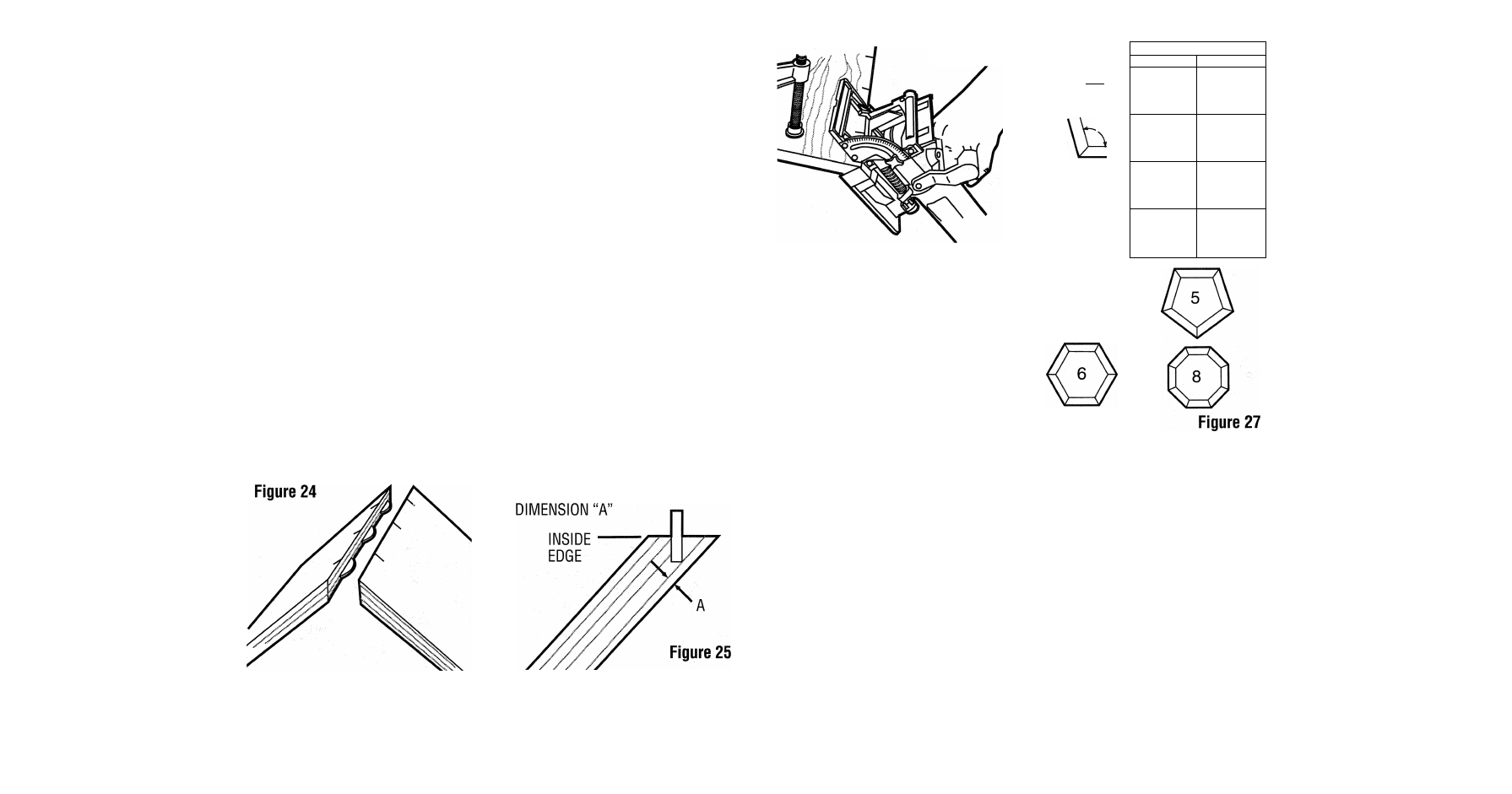
F. For joints other than 90° see outside registration column Figure 27 for
proper fence angle setting.
The above method will produce a joint where the outside surfaces of the joint
are aligned. If you wish to produce a joint where the inside surfaces are
aligned, use the following procedures for a 90° joint.
POSITION BISCUIT CLOSER TO
INSIDE EDGE TO INCREASE
Figure 26
REVERSE 45° BEVEL: ALLOWS
OUTSIDE REGISTRATION ON
MITER JOINTS
(NOTE:
The tool is registered against
the outside surface.)
8
JOINT ANGLE
^0°
108
°
^35"
FENCE ANGLE SETTING
OUTSIDE REGISTRATION
INSIDE REGISTRATION
90“
45“
81“
54“
75“
60“
67.5“
67.5“
A. Position work pieces as they are to be assembled.
B. Layout biscuit locations on the inside of the angle.
C. Set up tool by setting fence angle to 45°. Set vertical fence adjustment so
that the biscuit is located toward the inside of the joint where material is
thicker. Select biscuit size so that the blade does not protrude through the
outside face of the material.
D. Clamp the work piece and align the tool as shown in Figure 28.
E. Make the plunge cut and repeat for all biscuit locations.
F. Glue, assemble and clamp the joint.
G. For joints other than 90° see inside registration column in Figure 27 for
proper fence angle setting.
11