Index, Warning, Jcaution – Bolens 137-465A User Manual
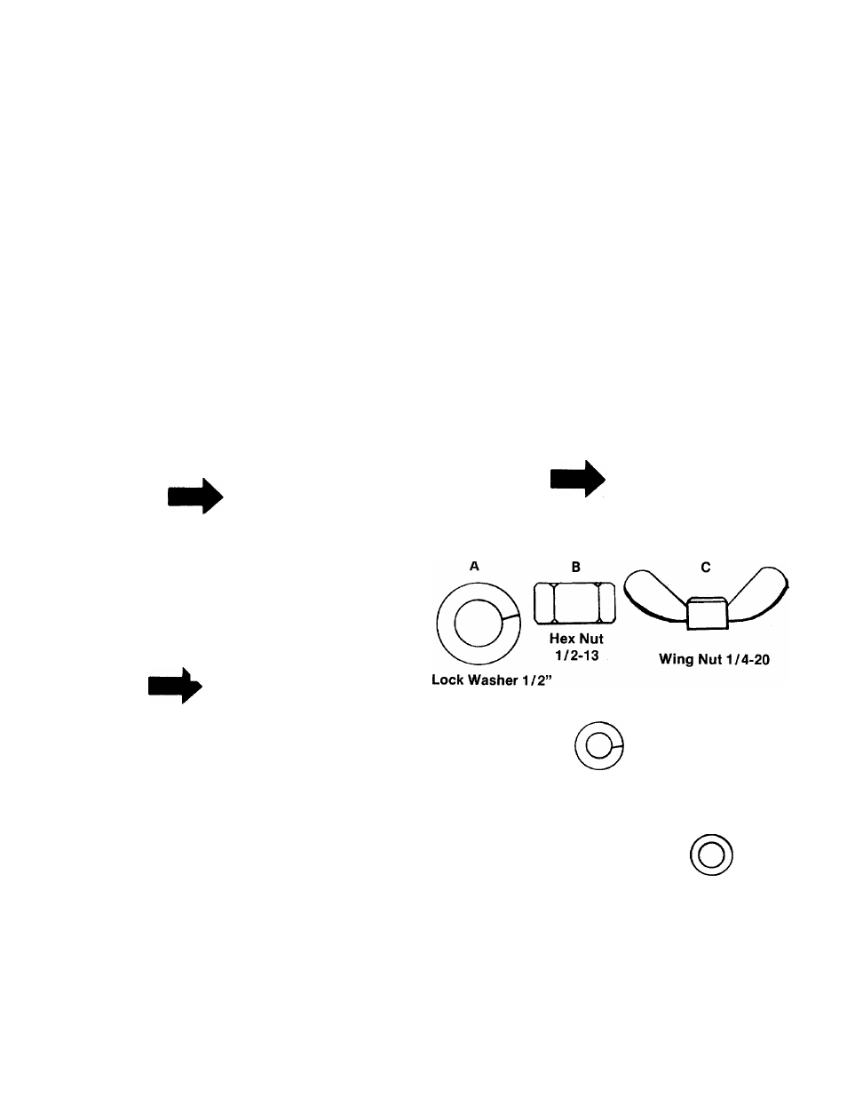
Page 3: Note, Important, Tire pressure, Hex bolt 1/4-20x5/8, Hex nut 1/4-20, Belleville washer 3/8, Figure 1. hardware supplied
Attention! The text in this document has been recognized automatically. To view the original document, you can use the "Original mode".
INDEX
Safe Operation Practices..............................................2
Index and Assembly..................................................... 3
Battery Information....................................................... 4
Controls......................................................................... 6
Operating Instructions..................................................9
Lubrication................................................................... 10
Adjustment................................................................... 12
Belt Removal............................................................... 13
Off-Season Storage.....................................................16
Trouble Shooting Chart (Recoil Model).................... 17
Trouble Shooting Chart (Electric Model)................ .18
Schemat for Electrical System (Recoil Start)... 19
Schematic for Electrical System (Electric Start).20
Differential Breakdown.............................................. 21
Transmission Breakdown...........................................22
Deck Linkage............................................................... 23
Illustrated Parts for Rider....................... 24, 26, 28, 30
Parts List for Rider................................... 25, 27, 29, 31
Parts Information....................................... Back Cover
GRASS
CATCHER
Model
No.
197-015A
is
available as optional equipment for the mowers
shown in this manual.
i
WARNING
The mower should not be operated
without the entire grass catcher or
chute deflector in place.
A.
jCAUTION
Installation of tire to rim :
1. Lubricate tire beads and rim flanges.
2. Do not exceed 30 P.S.I. when seating
beads.
3. Adjust to recommended pressure after
beads are sealed.
NOTE
Under normal usage bag material is
subject to wear, and should be
checked periodically. Be sure any
replacement bag complies with the
mower manufacturer’s recommen
dations.
For replacement bags, use only fac
tory authorized replacement bag No.
764-0121.
IMPORTANT
After striking a foreign object, stop
the engine (motor). Remove wire
from spark plug, thoroughly inspect
the mower for any damage, and re
pair the damage before restarting
and operating the mower.
The steering wheel and seat, with the necessary
hardware, are easily assembled to the machine.
On the electric starter models, the battery must be
activated and installed as outlined in this section.
TIRE PRESSURE
FOR SHIPPING PURPOSES, THE TIRES ON
YOUR UNIT MAY BE OVER-INFLATED. TIRE
PRESSURE SHOULD BE REDUCED BEFORE
UNIT IS PUT INTO OPERATION. PRESSURE
SHOULD BE APPROXIMATELY 15 P.S.I. EQUAL
TIRE PRESSURE SHOULD BE MAINTAINED ON
ALL TIRES. MAXIMUM TIRE PRESSURE IS 30
P.S.I.
NOTE
Reference to right-hand or left-hand
side of machine is from the driver’s
seat facing forward.
Lock Washer 1 /4”
Hex Bolt
1/4-20x5/8
oi
Hex Nut
1/4-20
H
Hex Lock Nut
3/8-16
Belleville Washer 3/8”
FIGURE 1. HARDWARE SUPPLIED
Step 1. Remove the lawn mower and all parts
from the carton. Make certain that all
loose parts and literature have been
removed before the carton is discarded.
Step 2. Place steering wheel over steering shaft.