Note, Adjusting carburetor choke, To adjust – Bolens 137-465A User Manual
Page 13: Preparing for belt removal, Warning, Mowing unit belt replacement
Attention! The text in this document has been recognized automatically. To view the original document, you can use the "Original mode".
Dimension “B” should be approximately 1 /8” less
than Dimension “A”.
A. ) To increase Dimension “B”, screw tie rod into
tie rod end.
B. ) To decrease Dimension “B”, unscrew tie rod
from tie rod end.
C. ) Reassemble tie rod. Check dimensions.
Readjust if necessary.
NOTE
To insure safe operation of your
unit, ALL nuts and bolts must be
check periodically for correct tight
ness.
FIGURE 26. CARBURETOR ADJUSTMENT
ADJUSTING CARBURETOR CHOKE
Proper choke operation is dependent upon proper
adjustment of remote controls on the powered
equipment.
To Check Operation of Choke-A-Matic Controls:
Move control lever to CHOKE position. (See figure
7.) The carburetor choke should be closed.
NOTE
The air cleaner can be removed to
check the operation of the choke.
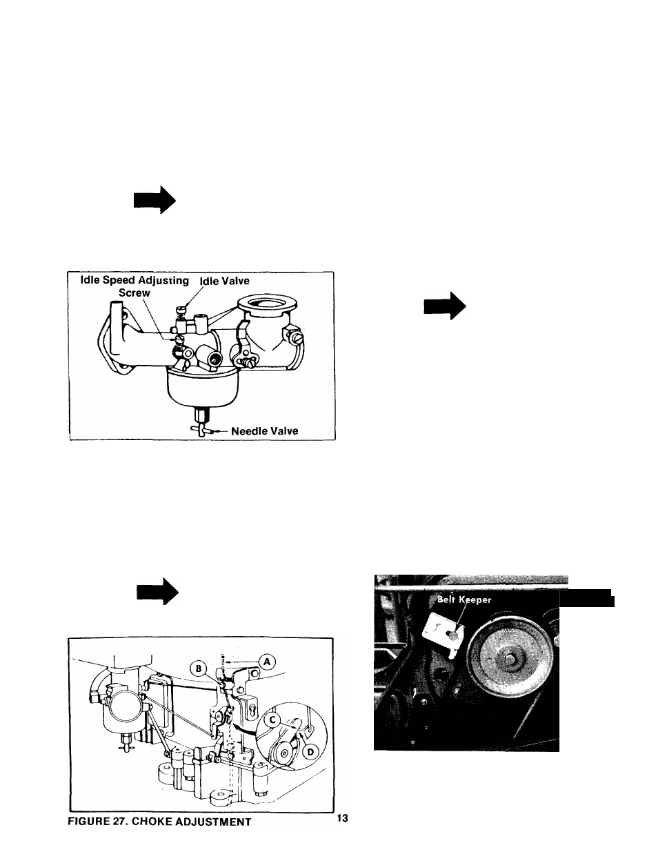
To Adjust:
Place control lever on equipment in FAST (High
speed) position. Loosen control casing clamp
screw B. Move control casing A and wire until
lever D touches choke operating link at C. Tighten
casing clamp screw B. See figure 27.
PREPARING FOR BELT
REMOVAL
1.
To prevent gasoline from leaking from the
engine, remove the fuel tank cap, place a
piece of thin plastic over the neck of the fuel
tank and screw on the cap.
2. Disconnect the spark plug wire and ground it
against the engine.
NOTE
If the unit is equipped with a battery,
continue with step 3.
3.
Remove the battery to prevent acid from
leaking.
WARNING
Disconnect the negative terminal
first and connect last when instal
ling the battery.
MOWING UNIT BELT REPLACEMENT
Step 1. Place the shift lever in the disengaged
position. See figure 9.
Step 2. Remove the belt keeper and large bolt on
the engine pulley. See figure 28.
/
Large
Bbit
FIGURE 28. BELT KEEPER
Step 3. Unhook the belt from the engine pulley.
See figure 29.