Securing the cables (hardware e), Attaching the starter rope (hardware c), Installation of wheels (hardware f) – Bolens 112-428R372 User Manual
Page 6
Attention! The text in this document has been recognized automatically. To view the original document, you can use the "Original mode".
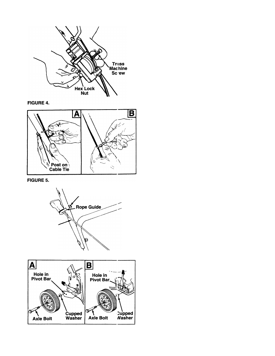
4. Place the control box on the upper handle just
below the end of the control handle as shown in
— figure 4. Secure with hardware removed in step
one by placing hex lock nut into the indent on the
inside of the control box. Screw the truss machine
screw into the hex lock nut.
SECURING THE CABLES (Hardware E)
Secure cables to the left side of the handle as follows.
A
WARNING: When attaching the control
cables, the cables must be routed to
avoid contact with all sharp edges and
hot surfaces to prevent damage to the
cables, which will render the controls
inoperative.
Insert posts on cable ties into holes provided on
the handles, one on the upper handle and two on
the lower handle. The holes may be either on the
inside or outside of the handles. See figure 5A.
Secure the cables with the cable ties. See figure
5B. Trim excess ends of cable ties.
Hex Lock
Nut
FIGURE 6.
Starter
Rope
ATTACHING THE STARTER ROPE (Hardware C)
1. The starter rope is inside the top of the engine.
Additional rope may be wound around the starter
handle. If so, unwind the rope from the handle.
2. With the spark plug wire disconnected and
grounded, depress the blade control handle and
pull the rope out of the engine.
" 3. Place the rope guide around the starter rope, so
the rope guide is positioned as shown (bends
downward slightly). Insert the rope guide through
the side of the upper handle, and secure with hex
lock nut.
INSTALLATION OF WHEELS (Hardware F)
1. Insert axle bolts through wheels, then place
cupped washers on bolts (crowned side of wash
ers go against the wheels).
- 2. Attach the wheels to the pivot bar on the height
adjusters. Use the top hole in the pivot bar when
assembling the front wheels; use the rear hole in
the pivot bar when assembling the rear wheels.
See figure 7.
FIGURE 7.