Assembly instructions, Unpacking, Attaching the lower handle (hardware a) – Bolens 112-428R372 User Manual
Page 5: Attaching the upper handle (hardware b), Attaching the cdntrdl bdx
Attention! The text in this document has been recognized automatically. To view the original document, you can use the "Original mode".
ASSEMBLY INSTRUCTIONS
This owner’s guide covers various modeis of
mowers. Foiiow oniy those instructions which
pertain to your unit.
iMPORTANT: This unit is shipped WiTHOUT
GASOLiNE or OiL. After assembiy, service engine
with gasoiine and oii as instructed in the separate
engine manuai packed with your unit.
NOTE: Reference to right or ieft hand side of the
mower is observed from the operating position.
Toois Required for Assembiy
(1) Pair of Pliers
(1) Phillips Screwdriver
(1) 1/2" Wrench*
(1)7/16" Wrench*
*Or two 6" Adjustable Wrenches
Lower
Handie
Handie
Mounting
Bracket
FiGUREt
UNPACKING
1. Remove the lawn mower from the carton by
opening the top flaps and lifting the unit out. Be
careful of the staples. Make certain all parts and
literature have been removed from the carton
before the carton is discarded.
2. Disconnect the spark plug wire and move away
from the spark plug.
3. Stretch out all control cables with control box
attached to the left side of the mower and place
on the floor. Be careful not to bend or kink the
cables at any time during assembly.
4. Remove page four from this manual and lay the
contents of the hardware pack on the illustration
for identification.
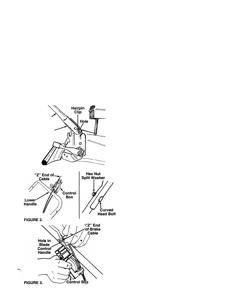
ATTACHING THE LOWER HANDLE (Hardware A)
1. Slide the control box over the lower handle so
that the cable with the “Z” end is routed above the
lower handle, and the other cable is routed below.
See figure 2.
2. Attach the lower handle by placing the bottom
holes in the lower handle over the weld pins on
the handle mounting brackets on the rear of the
deck.
" 3. Using a pair of pliers, squeeze one leg of the
lower handle against the handle mounting brack
et. Insert the hairpin clip into the hole on the weld
pin. See figure 1. Repeat on other side.
ATTACHING THE UPPER HANDLE (Hardware B)
1. Place the upper handle in position over the lower
handle. The hole in the side of the blade control
handle (attached to the upper handle) must be on
the left side.
2. Secure the upper handle to the lower handle
using the curved head bolts, split washers and
----- hex nuts as shown in figure 2.
ATTACHING THE CDNTRDL BDX
Attach the control box to the upper handle as follows.
1. Remove the truss machine screw and hex lock
nut from the middle of the control box using a
Phillips screwdriver. (Hold your finger over the
hex lock nut so it stays inside the control box so
you can unscrew the truss machine screw.)
2. Make certain the blade control handle is on top of
the upper handle.
- 3. Holding the control box near the left side of the
upper handle (control box must be inside the han
dle), hook the “Z” end of the brake cable into the
control handle from the outside to the inside. See
figure 3.