Altec Lansing 9441A User Manual
Page 6
Attention! The text in this document has been recognized automatically. To view the original document, you can use the "Original mode".
Operating and Service Instructions for the Altec Lansing 9441A Power Amplifier
Max. Length of 2-wire cable in
feet
ZL — Zo
= DF
DCR/ft
where
ZL is thé load impedance
to comiect to the amp
lifier;
Zo is the amplifier’s out
put impedance (0.08 ohms
for the 944lA);
DF is the minimum per-
mi.ssible damping factor at
tlie load; and
DCR/ft i.s the DC resis
tance of the 2-wire cable
per foot from Table I.
The same equation can be used to
calculate the maximum cable
length in meters by substituting
the DCR per meter value from
Table I.
Let’s use the equation. Suppose
ZL equals 8 ohms, Zo = 0.08
ohms, and the minimum damping
factor at tlic load is 25. In addi
tion, IS GA cable is preferred.
Then, the maxiinxim length of 18
GA cable which can be used to
achieve a damping factor of 25 fit
the load is;
8
25
(0.08)
0.01302 n/ft
IS.4 feet
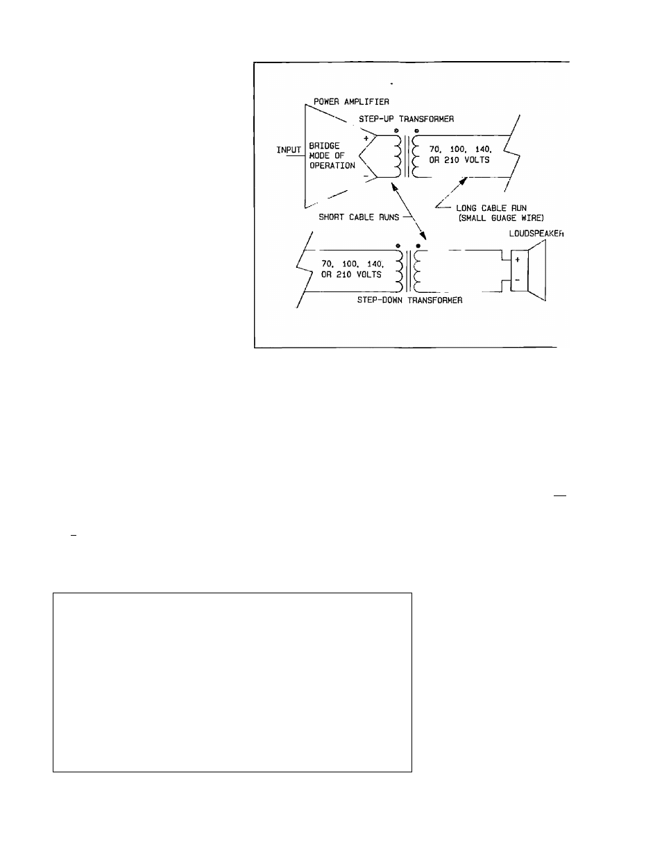
Figure 5 High-voltage Distribution System
Sometimes it may be necessarj' to
locate the speaker 100 feet or
more away from the amplifier. In
this situation, a much larger
gauge cable is required. However,
this may not be jiractical or eco
nomical. The size of the 2-wire
cable can be greatly reduced by
stepping up the output voltage of
tlie amplifier to 70, 100, 140, or
210 volt, using an output trans
former, then stepping down the
voltage at the load. Such a system
is shown in Figure 5.
length of v-v/ire
I'he maximum
cable in this situation can be
approximated from the following
equation:
Max. Length of 2-wire o;
feet
i e
in
(Pout)(DCR./ft)
J_
DF
Zo
ZJ.
where
Table I 9441A Power Losses in 2-wire Speaker Cable
Power
Cable Cross-
Power
AWC,
nc:n/fi
I.ciss/n
Socllonal
UCR/iTicler
I^ishKlcr
(0Л)
(îVil)
(willt.s/(1)
area (iiim*)
(U/m)
(woUs,/m)
G
0.Ь0Ы8I
0.0075
13.30
0.00204
0.0247
8
0.00121
0.0i:)4
8.30
0.0042I
0.0394
10
0.0020'!
0.0191
5.26
0.00669
0.0626
12
0.00324
0.0303
3.31
0.01063
0.0052
И
O.OO.'il.'i
0.0482
2.08
0.01691
0.1581
IG
0.0081!)
0.0767
I.3I
0.02085
0.2508
18
0.01302
0.1218
0.82
0.042S9
0.39Î16
20
0.02070
0.1935
0.52
0.06764
0.6288
22
0.03202
0.:t073
0.33
0.10658
0.9860
V is the stejipod-up
voltage of the system;
Pout is the rated output
power of the amidifier;
Zo is the output imfied-
ance of the amplifier (0.08
ohms for the 9441A r,
ZL is the load impeo.mce;
DCR/ft
is
tb.
DC
resistance of th: 2-wire
cable per foot from Table
I; and
DF
is
the
minimum
permissible damping fac
tor at the load.
ALTEC LANSING* CORPORATION
©
a Mark IV Company