Addendum – Altec Lansing 9441A User Manual
Page 19
Attention! The text in this document has been recognized automatically. To view the original document, you can use the "Original mode".
ADDENDUM
TO THE ALTEC LANSING 9441A
OPERATING AND SERVICE INSTRUCTIONS
Operating and Service Instructions for the Altec Lansing 9441A Power Amplifiei
The following is a change to the Electrical Instructions of the Altec Lansing 944lA Power Amplifier found on pages
1 and 2 of the Operating and Service Instructions (Part Number 42-02-037980).
1.2
220/240 V ac, 60/60 Hz Power' Connections
The power transformer has two 120 volt primary windings which can be connected in parallel for 120 V ac line
voltages, or in series to meet 220/240 V ac requirements. Use the following procedures to re-strap the i-i-imary of
the power transformer for 220/240 V ac applications.
1. Make sure the amplifier is not connected to any power source.
2. Remove and save the ten screws securing the top cover. Refer to Figure 1 for the exact screw locations.
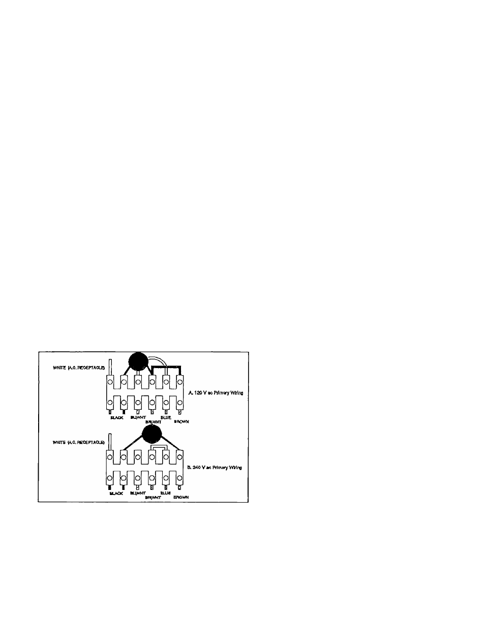
3. Locate terminal block TBl located behind the AC main power switch. Reconnect the leads as showr- in Figure
2
.
4. Install the top cover with the ton screws previously removed.
5. Install the 2.0A fuse, T2.0A /250V slo-blo or equivalent.
6. Install the 230 Vac 50/60Hz and the '1'2.0A/250V decals in the proper positions.
Figure 2 Primary wiring Configuration for 120 V ac and 220 V uc
Printed in U.S.A. 7/92
Revision 1
42-02-038412