Altec Lansing 9441A User Manual
Page 3
Attention! The text in this document has been recognized automatically. To view the original document, you can use the "Original mode".
Operating and Service Instructions for the Altec Lansing 9441A Power Amplifier
1 ELECTRICAL
Two amplifier models are
available. One model has a 50/60
Hz power transformer with two
120 V ac primary windings. These
windings may be wired in parallel
or series for operation at either
120 V ac or 220/240 V ac. The
other amplifier model is for export
into countries where tlie ac line
voltage is 100 volts, 50/60 Hz. The
next two sections refer to the first
model witli the dual 120 V ac pri
mary windings.
1.1
120 V ac, 50/60 Hz
Power Coimections
'rhe amplifier is provided
with the primary of the power
transformer slrappcil for 120 V ac
operation from the factory. Refer
to Figure 2 for the wirijjg deUiils.
WARNING:
Verify that the power
transformer’s
priinaiy
circuit
con
figuration
is
correct
for
the
in
tended
ac
line
voltage
BEFORE
applying power to the amplifier.
1.2
220/240 V ac, 50/60 Hz
Power Connections
The power transformer
has two 120 volt primary windings
which can be connected in parallel
for 120 V ac line voltages, or in
series to meet 220/240 V ac re
quirements. Use the following
procetlures to re-strap the primary
of the power transformer for
220/240 V ac applications.
1.
Malce sure the amplifier is
not connected to any
power source.
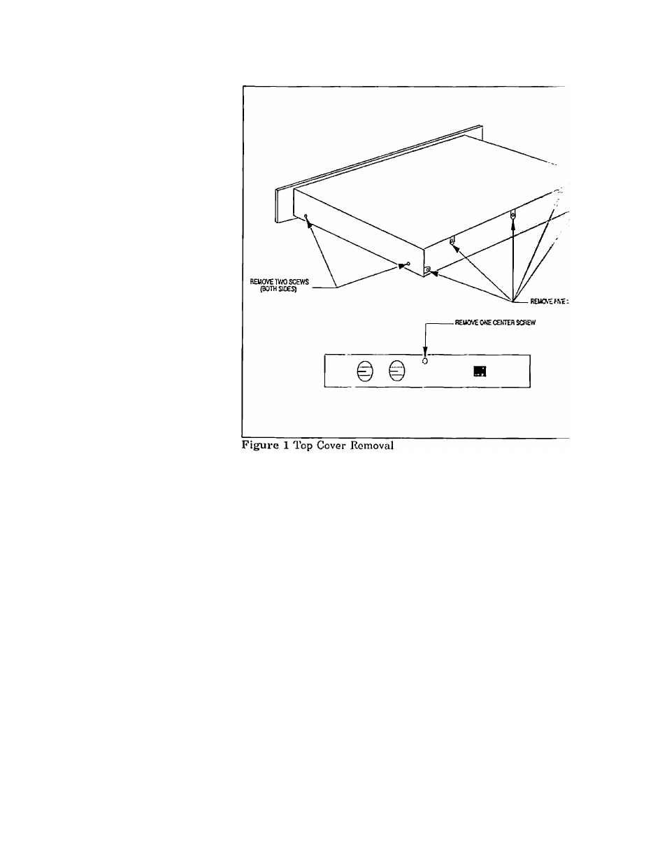
2.
Remove and save the ten
screws securing the top
cover. Refer to Figure 1
for the exact screw loca
tions.
3.
Locate terminal block TBl
located behind the AC
main power switch. Re
connect the leads as
shown in Figure 2.
4.
5.
6
.
Install the top cover with
the ten screws previously
romovetl.
Install the 2.0 A fuse,
T2.0A /250V slo-blo or
equivalent.
Install the 230 Vac 50/-
60Hz and the T2.0A/250V
decals
in
the
proper
positions.
INSTALLATION
2.1
Rack
Mounting
The amplifier may be in
stalled in a standard 19 inch
equipment rack. It requires 1.75
inches of vortical rack space and
secures to the rack cabinet with
the-four rack mount screws and
cup washers provided in the hard
ware kit.
2.2
Ventilation
The amplifier m.;;;t be
adequately vontil.ntod tn ir.'oid ex
cessive temjjerature rise,
i
si;ould
not be used in areas where the
ambient temperature exceeds SO'C
(122°F). To determine i .imbi-
ent air temperature, opemte the
system in the rack until the tem
perature stabilizes. Mea'"ro the
ambient air with a bulb-type ther
mometer held at the botloin of the
uppermost amplifier. Dc tmt let
the thermometer touch the netal
chassis because the chassis will be
hotter than the ambient a:.-. If the
air temperature exceerls 50°C
(122°F), the equipment siiould be
spaced at least 1.75 inches apart
or a blower installed to provide
sufficient air movement within
the cabinet.
WARNING:
Do
not operate the
amplifier
within
a
completely
closed unventilated housing.
ALTEC LANSING* CORPORATION
•
a Mark IV Company