Altec Lansing 9441A User Manual
Page 5
Attention! The text in this document has been recognized automatically. To view the original document, you can use the "Original mode".
Operating and Service Instructions for the Altec Lansing 9441A Power Amplifier
SOURCE
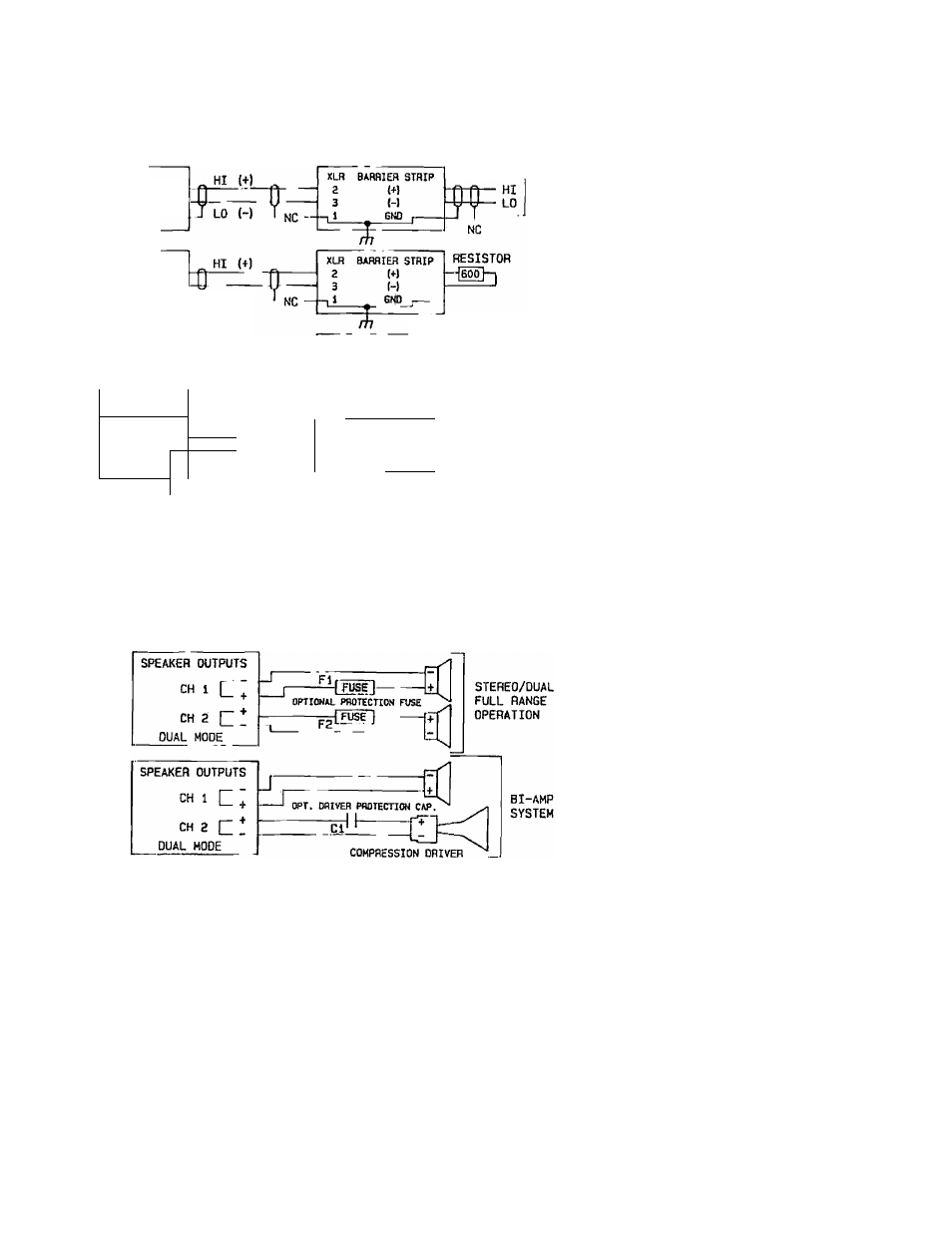
AMPLIFIER'S INPUTS
BALANCED
SOURCE
AUX OUTPUTS
(USER OPTIONS)
BAL
OUTPUT
BALANCH3
SOURCE
H/600 OHM
TERMINATION
UNBALANCED
SOURCE
LO (-)
HOT
SINGLE-ENDEO AUX OUTPUT
'G j
XLn BAFIflIEH STRIP
2
(+)
3
(-)
6Ю ¡-
----- -------
UNBALANCED
HOT
SOURCE
J COM
/,
1
7lr ^
Ж.
HOT
COM
r
NC
ЯЛ
ВАИЙ1ЕП STHIP
2
(t)
Э
H
—
t i
E.ND ,-----
%
NC
HOT
COM
KEEP
CABLE
RUNS
UNDER
6
f t
OR 2 m
Figure 3 Topical Input Connections
AMPLIFIER'S OUTPUTS
LOUDSPEAKER LOADS
SPEAKER OUTPUTS
CH 1 L‘
eniOGE OUTPUT Q I I
CH
г
BRIDGE MODE
=0]
HIGH POWER
FULL RANGE/
SUBWOOFER
Figure 4 'Topical Output Connections
to control unwanted speiiker cone
movements. When a signal drives
a woofer, current flowing through
the voice coil creates a magnetic
field. This field interacts with the
permanent magnetic field in the
gap and forces tlie combination
cone and voice coil assembly to
move outward. When the signal is
removed, the assembly moves
inward but its niomontum cmises
it to overshoot its resting point.
This overshoot will dampen itself
out eventually but the unwanted
movements can add consitlerable
distortion products to tlu touiul.
In the process of moving hv.vard
through the magnetic fieUh the
voice coil assembly generatos a
current of opposite polarity tn the
original signal. This current in
duces a voltage or "back EMF”
which travels through the speaker
wire to the amplifier's '.utput.
The lower the amplifier’i. output
impedance, the faster tl.o over-
slioot of the voice coil will dampen
out. The output impedii'io; of an
amplifier can be calculated by
dividing the rated output linped-
ancG, typically 8 ohms, uy the
damping factor. The 944
i A
has a
damping factor rating ;
100
which corresponds to an 4Utput
impedance of 0.08 ohni.s.
3.5.1
C a l c u l a t i n g
t h e
Maximum
Length
of
Cable for a Spenified
Damping Factor Spec
ification at the Load
Tlie damping factor rating
is typically never realiz-т-: at the
load because of the rosisLunce of
the cable (and other facLnia such
as the contact resistance of an
output relay or the resistance of
an output fuse). Tlie damping fac
tor at the load should be 30 for
general paging systems ami 50 for
high fidelity music systcm.s. Econ
omics usually dictate, however,
that these numbers are cut-in
half. The resulting dampiiig factor
at the load should be based on ex
perience and customer satis
faction. Once a minimum; c ciiiping
factor is determined for => partic
ular type of installation, the fol
lowing equation can calculate the
maximum length of 2-wire cable
which can be used to achieve the
minimum damping factor
.s^x
cified
at the load:
ALTEC LANSING* CORPORATION • a Mark TV Company