Additional features – Black & Decker 9400 User Manual
Page 6
Attention! The text in this document has been recognized automatically. To view the original document, you can use the "Original mode".
SPEED— DRIVE BELT
ARRANGEMENT: TURN OFF AND
UNPLUG DRILL PRESS BEFORE
MAKING ANY ADJUSTMENTS.
ALWAYS WEAR EYE PROTEC
TION. Your drill press is capable of
running at fiv^ different speeds,
each one determined by the
arrangement of the drive belt and
pulley system inside the top of the
Motor and Drive Unit. A handy chart
that describes how to select a
particular speed is attached to the
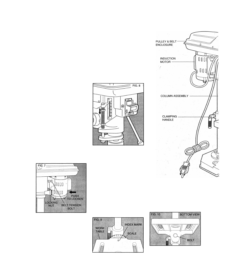
inside of the drive belt cover.
To select a speed, loosen the
locking nut and screw the belt
tension bolt into the drive unit
(Figure 7) .Push the motor forward
to loosen the drive belt. Adjust the
belt as desired, referring to the chart.
Retighten the belt by pushing back
on the motor. Back the belt tension
bolt out of the drive unit until the belt
is snug on the pulleys. Tighten
locking nut to motor housing to lock
the belt tension bolt. NOTE: It is not
necessary to put great pressure on
the drive belt. Just remove most of
the slack. The belt should be able to
slip in case the drill bit jams in the
hole.
DRILLING DEPTH CONTROL:
On the left side of the Motor and
Drive Unit is the Drilling Depth
Control Assembly. To set the drilling
depth (from 0 to 2"), first raise the
chuck to its full up position. (It
should do this automatically with
spring pressure.)
Adjust by hand, the depth
pointer shown in Figure 8 so that it
points to zero and rotate both hex
nuts counterclockwise until they are
both up next to the pointer. Lower
the chuck using one of the three
handles to the desired depth. Hold
the chuck in place while you screw
down the lower hex nut on the
Drilling Depth Control Assembly, as
shown in Figure 8. Screw the nut
down until it contacts the boss
protruding from the side of the Drive
Unit shown in Figure 8.
Lock the nut in place by
screwing the top hex nut down
against the lower one. Release the
handle letting the chuck rise to its
full height.
When you^drill a hole and the
lower hex nut “bottoms ouf on the
boss, the drill bit will continue to
rotate but will go no deeper.
Additional Features
TILTING THE WORK TABLE:
The Tilting Work Table is designed to
tilt up to 45° left and right and includes a
precision scale marked In degrees
from 0 to 45°, as shown in Figure 9.
To adjust the table to some angle
other than 0° (horizontal), loosen the
large bolt located under the Work
Table, as shown in Figure 10.