Grounding, Instructions, Motor – Black & Decker 9400 User Manual
Page 4: Lubrication & maintenance, Unpacking your drill press, Grounding instructions
Attention! The text in this document has been recognized automatically. To view the original document, you can use the "Original mode".
Grounding
Instructions
ALL GROUNDED, CORD-
CONNECTED TOOLS: In the event
of a malfunction or breakdown,
grounding provides a path of least
resistance for electric current to
reduce the risk of electric shock.
This tool is equipped with an electric
cord having an equipment-grounding
conductor and a grounding plug.
The plug must be plugged into a
matching outlet that is properly
installed and grounded in accor
dance with all local codes and
ordinances.
Do not modify the plug pro
vided—If It will not fit the outlet, have
the proper outlet installed by a
qualified electrician.
Improper connection of the
equipment-grounding conductor can
result In a risk of electric shock. The
green (with or without yellow stripes)
is the equipment-grounding conduc
tor. If repair or replacement of the
electric cord is necessary, do not
connect the equipment-grounding
conductor to a live terminal.
Check with a qualified electri
cian or serviceman if the grounding
instructions are not completely
understood, or if in doubt as to
whether the tool Is properly
grounded.
Use only 3-wire extension cords
that have 3-prong grounding plugs
and 3-pole receptacles that accept
the tool’s plug.
Repair or replace damage or
worn cords Immediately.
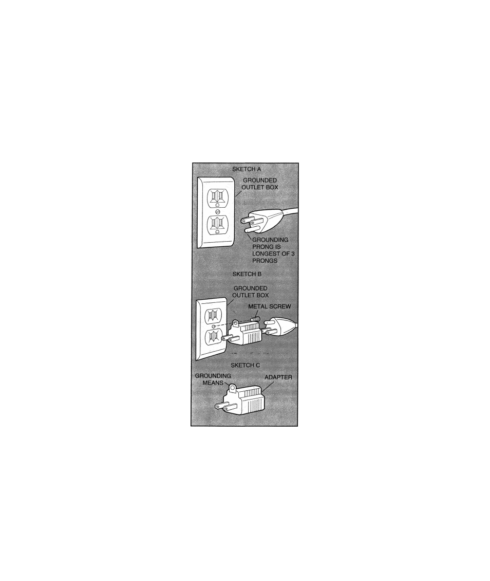
GROUNDED, CORD-
CONNECTED TOOLS INTENDED
FOR USE ON A SUPPLY CIRCUIT
HAVING A NOMINAL RATING
LESS THAN 150 VOLTS: This tool
Is Intended for use on a circuit that
has an outlet that looks like the one
illustrated in Sketch A. The tool has
a grounding plug that looks like the
plug illustrated in Sketch A. A
temporary adapter, which looks like
the adapter Illustrated In Sketches B
and C, may be used to connect this
plug to a 2-pole receptacle as shown
in Sketch B if a properly grounded
outlet (Sketch A) is not available.
The green-colored rigid ear, lug, etc.
extending from the adapter must be
connected to a permanent ground
such as a properly grounded outlet
box. The temporary adapter should
be used only until a properly
grounded outlet (Sketch A) can be
installed by a qualified electrician.
Adaptor shown in sketches B & C is
not for use in Canada.
Motor
Be sure your power supply
agrees with the nameplate marking.
120 volts 50/60 Hz means alternating
current (normal 120 volt, 60 Hz
house current). A voltage decrease
of more than 10% will cause loss of
power and overheating. All B&D
tools are factory tested; if this tool
does not operate, check the power
supply.
Lubrication &
Maintenance
Permanently lubricated ball
bearings are used throughout your
Drill Press and periodic lubrication is
not required. In the unlikely event
that your Drill Press should ever
require service, take it to your local
Black & Decker Service Center or
other qualified service facility.
Service Center addresses are listed
on the owner’s registration card
packed with your tool. Do not
attempt to repair the tool yourself.
There are no user-serviceable parts
inside.
A film of any light machine oil on
the unpainted parts of your Drill
Press will prevent surface rust from
forming.
IMPORTANT:
YOUR DRILL PRESS IS
DRIVEN BY A RUBBER BELT. IF
THIS BELT IS EXCESSIVELY
TIGHT ON ITS PULLEYS AND A
PARTICULARLY LARGE DRILL
BIT IS USED, THERE EXISTS THE
POSSIBILITY OF A MOTOR
OVERLOAD WHICH WILL SERI
OUSLY DAMAGE YOUR MOTOR.
WHEN ADJUSTING THE
RUBBER BELT, MAKE IT TIGHT
ENOUGH TO REMOVE MOST OF
THE SLACK BUT MAKE SURE
THAT IT’S ABLE TO SLIP
ENOUGH ON THE PULLEYS TO
PREVENT A MOTOR OVERLOAD
CONDITION.
Unpacking Your Drill
Press
Your new drill press carton
contains the four main elements of
your drill press, plus the hardware
needed to assemble it. Each of the
four main elements is wrapped in a
plastic bag and placed in its own
pocket in the foam carton liner.
The four main elements of your drill
press are:
1. The Motor and Drive Unit