Assembly, Controls – Black & Decker 9400 User Manual
Page 5
Attention! The text in this document has been recognized automatically. To view the original document, you can use the "Original mode".
2. The Base Plate
3. The Column Assembly
4. The Work Table
Before beginning assembly,
examine the contents of the card
board box and the plastic bag
packed with your Drill Press. The
box contains the chuck and chuck
key and the plastic bag contains all
the rest of the hardware needed to
assemble the tool.
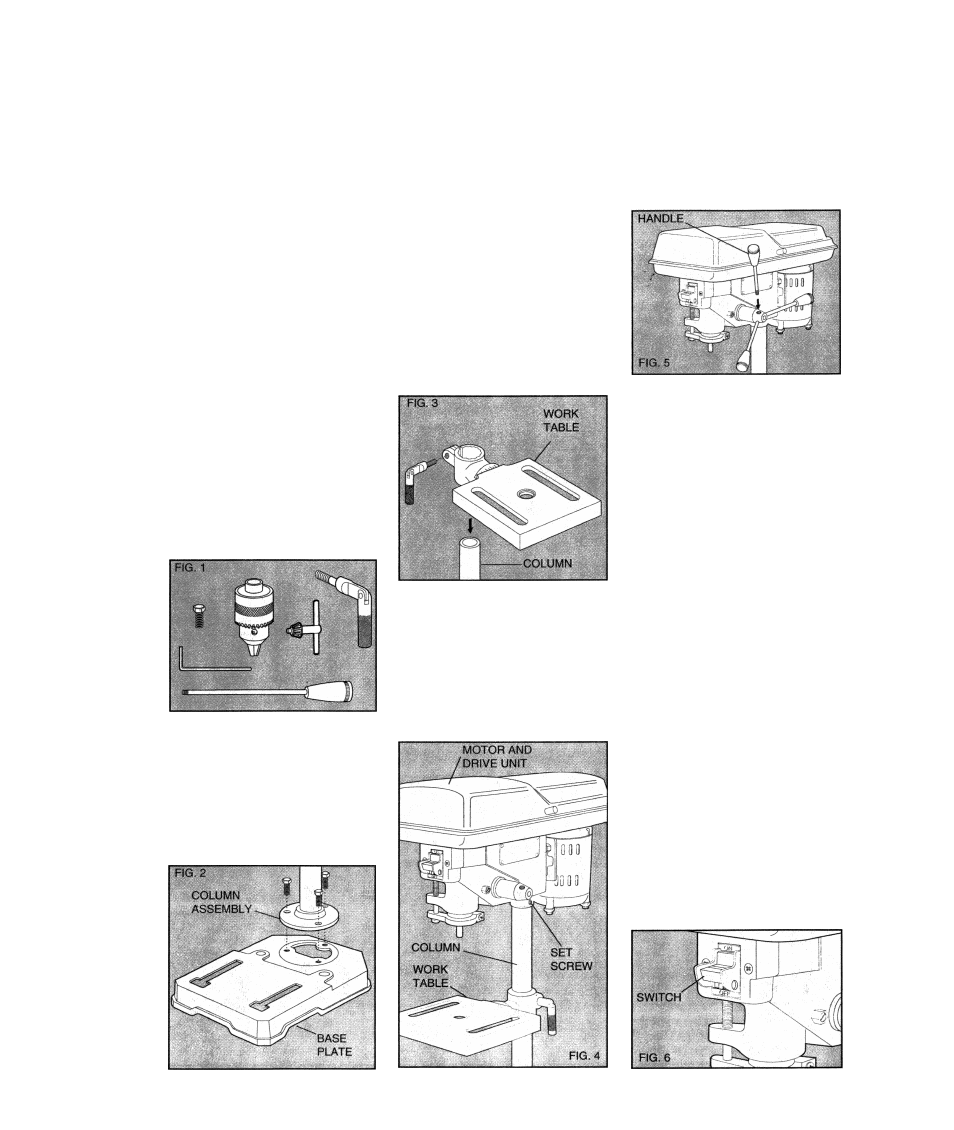
The contents of the plastic bag
are displayed In Figure 1. Take a
few minutes and become familiar
with the nomenclature used to
describe the various components,
a. Column Bolts (3)
Table Clamping Screw (1)
Handles (3)
Chuck (1)
Hex Wrench (1)
b.
c.
d.
e.
f. Chuck Key (1)
Assembly
Using the 3 Column Bolts,
install the Column Assembly to the
Base Plate, as shown in Figure 2.
Place the Base Plate/Column
Assembly on a smooth, flat surface.
Install the Work Table down
over the column, machined surface
up, as shown in Figure 3. Insert the
Table Clamping Handle into the
collar at the back of the work Table,
as shown in the figure. Make sure
that you insert the threaded end of
the handle THROUGH the un
threaded side of the collar BEFORE
engaging the threads. Position the
Work Table about midway on the
column and directly over the Base
Plate.
Install the Motor and Drive Unit
on top of the column and make sure
that it fits firmly against the shoulder
in the column. Position the drive
spindle directly over the Work Table
and tighten the set screw in the side
of the Motor and Drive Unit, as
shown in Figure 4.
Install the three handles, as
shown in Figure 5.
The small cardboard box stored
with the plastic hardware bag
contains the Chuck and Chuck Key.
Before installing the chuck thor
oughly clean the tapered spindle
and the mating cavity in the chuck
with a non-flammable solvent, on a
rag, to remove the oily residue on
each surface. To install the Chuck,
press it firmly up onto the tapered
drive spindle. You may tap It a few
times with a plastic hammer to
assure a firm fit. DO NOT USE A
STEEL HAMMER. No threads are
involved. NOTE: The Chuck Key has
a built-in spring to keep it from being
accidentally left in the chuck. Do not
disable or circumvent this safety
feature in any way. To do so will
create a potentially hazardous
condition
Controls
SWITCH: The switch is located on
front of the drill press, as shown in
Figure 6. To turn the tool “ON”, flip the
toggle upward and to turn the tool
“OFF’, flip the toggle down. The switch
will stay in either position without being
held. For safety the red switch button
may be removed when the switch is in
the off position. This will prevent
unintentional starting by others.