Bevel angle adjustment, Guide edges, Figure 5 – Black & Decker cat 3027-90 User Manual
Page 7
Attention! The text in this document has been recognized automatically. To view the original document, you can use the "Original mode".
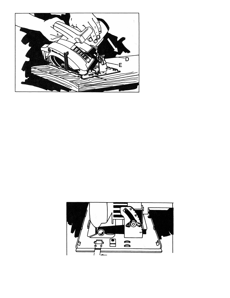
FIGURE 4
BEVEL ANGLE ADJUSTMENT
DISCONNECT THE SAW FROM THE POWER SUPPLY BY PULLING THE PLUG,
BEFORE MAKING THIS, OR ANY OTHER ADJUSTMENT! On the front of the saw
is a bevel angle adjustment device (Figure 4) consisting of calibrated quadrant
“E” and a knob “D”. To set the saw for a bevel cut, loosen knob and tilt shoe
to angle desired. Retighten knob firmly.
CAUTION: When making bevel cuts, place one hand on the motor housing as
shown in Figure 4. Exert only enough pressure in the direction of the arrow to
keep the saw shoe flat on the work. This will insure an accurate bevel cutting
angle and help prevent the blade from binding in the cut.
GUIDE ALONG PENCILLED GUTTING LINE
SO KERF FALLS IN WASTE STOCK —
GUIDE EDGES
Guide along the penciled cut
ting line so that the kerf falls
into the waste or surplus
material—See Figure 5.
DESIRED
- LENGTH -
OF STOCK
WASTE
OR
SURPLUS
STOCK
FIGURE 5
-KERF
An Adjustable Guide on
the front of the saw
shoe
has
two
guide
edges (Figure 6)—one
for vertical cutting, and
one for 45‘’bevel cut
ting. These edges en
able you to guide the
saw along penciled lines,
and the edges line up
with the left (inner) side
of the saw blade. This
makes the slot or "kerf"
cut by the moving blade
fall to the right of the
guide mark.
45* BEVEL CUT 1 GUIDE
0* VERTICAL CUTJ EDGES
FIGURE 6