Bryant 342S User Manual
Page 6
Attention! The text in this document has been recognized automatically. To view the original document, you can use the "Original mode".
S E P / 0 9 / 2 0 0 8 / T U E 0 3 : 3 4
UTC TECH PUB
F A X N o , 3 1 7 2 4 0 5 6 6 2
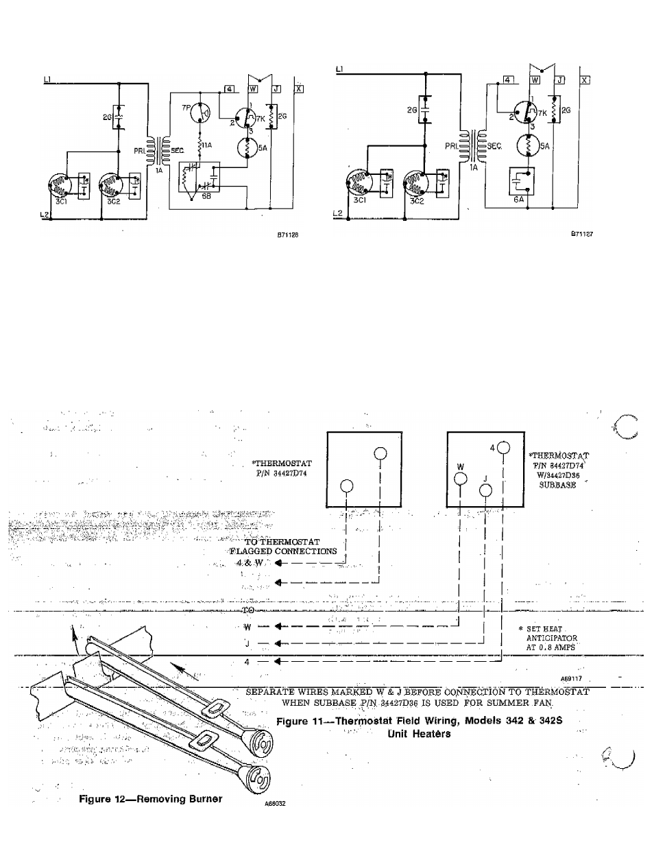
SIZE 400 UNIT HEATER WIRING DIAGRAMS
Figure 9—With 733 Pilot Installed
Figure 10—With 732 Pilot Installed
LEGEND
1A
Transformer
7K
Tamp Limit Control—
2G
Fan Relay—^N.0,
SPOT—N.C.
3C1
Fan Motor
7P
Pressure Switch—
3CS
F$n Motor
SPST^N.;0,
5A
Automatic Gas Valve
11A
Resistor
6A
Pilot Switch—N.O.
If wires are replaced, use 19 AWG
{Nons on Propane)
1S0° C,, 3/64-inch thick insulation.
6B
Pilot with Auto.,
Ignition Coil
6
-
See also other documents in the category Bryant Conditioners:
- EVOLUTION 577D----A (40 pages)
- Packaged Air Handling Units 542J (4 pages)
- Air Handling Units 524J (36 pages)
- 591B (12 pages)
- Electric Air Conditoner 597C (28 pages)
- 599C (2 pages)
- PREFERREDT A07044 (80 pages)
- 502A (8 pages)
- 564A (20 pages)
- 702B (28 pages)
- 538J-18-1 (12 pages)
- 764A (24 pages)
- 580J*04--12 (73 pages)
- AIR CONDITIONERS 564A (20 pages)
- 561G (2 pages)
- PURON PLUS 598B (40 pages)
- R-410A 583B (30 pages)
- 538MNQ (10 pages)
- EVOLUTION 707D (4 pages)
- 463AAC008BA (19 pages)
- DURAPACK 558F (70 pages)
- 664A (4 pages)
- 479 D (13 pages)
- 569D (84 pages)
- Legacy Air Conditoner H3A (6 pages)
- 561S (2 pages)
- R-22 561G (6 pages)
- 594D (24 pages)
- 450D (10 pages)
- 574D (32 pages)
- DE LUXE 12 SEER 552A (36 pages)
- R-22 (52 pages)
- CD5A (8 pages)
- 564B (20 pages)
- Air Conditeners 180A (16 pages)
- 677C--A (36 pages)
- 559F (48 pages)
- LEGACY 564B (4 pages)
- s 123A (6 pages)
- 598A (8 pages)
- Air Cooled Condensing Units 569C (20 pages)
- 580J*08--14D (85 pages)
- Electric 594D (24 pages)
- 588A (28 pages)
- 577C (8 pages)