Bryant 342S User Manual
Page 5
Attention! The text in this document has been recognized automatically. To view the original document, you can use the "Original mode".
S E P / 0 9 / 2 0 0 8 / T U E 0 3 : 3 3 P M UTC TECH PUB
F A X N o , 3 1 7 2 4 0 5 6 6 2
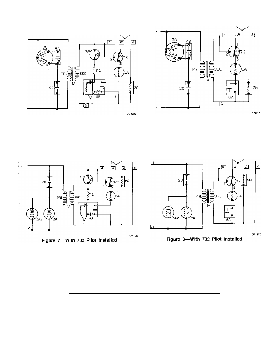
SIZES 175 THRU 250 UNIT HEATER WIRING DIAGRAMS
Figure 5—With 733 Pilot Installed
Figure 6—With 732 Pilot Installed
SIZE 300 UNIT HEATER WIRING DIAGRAMS
LEGEND
1A Tran3fùi‘rYier
6B Pilot with Auto.
2G
Fan Relay—N,0.
3A.
Fan Motor
Ignition Coil
7K Temp Limit Control—
SPOT—N,C,
3A2
Fan Motor
7P
Pressure Switch —
3C
Fan Motor
S PST—N.O,
5A
Automatic Gas Valve
IIA
Resistor
6A
Pilot Switch—N.O.
If wires are replaced, use 18 AWG
(None on Propane)
150^ C„ 3/64-inch thick insulation.
^
5
-
See also other documents in the category Bryant Conditioners:
- EVOLUTION 577D----A (40 pages)
- Packaged Air Handling Units 542J (4 pages)
- Air Handling Units 524J (36 pages)
- 591B (12 pages)
- Electric Air Conditoner 597C (28 pages)
- 599C (2 pages)
- PREFERREDT A07044 (80 pages)
- 502A (8 pages)
- 564A (20 pages)
- 702B (28 pages)
- 538J-18-1 (12 pages)
- 764A (24 pages)
- 580J*04--12 (73 pages)
- AIR CONDITIONERS 564A (20 pages)
- 561G (2 pages)
- PURON PLUS 598B (40 pages)
- R-410A 583B (30 pages)
- 538MNQ (10 pages)
- EVOLUTION 707D (4 pages)
- 463AAC008BA (19 pages)
- DURAPACK 558F (70 pages)
- 664A (4 pages)
- 479 D (13 pages)
- 569D (84 pages)
- Legacy Air Conditoner H3A (6 pages)
- 561S (2 pages)
- R-22 561G (6 pages)
- 594D (24 pages)
- 450D (10 pages)
- 574D (32 pages)
- DE LUXE 12 SEER 552A (36 pages)
- R-22 (52 pages)
- CD5A (8 pages)
- 564B (20 pages)
- Air Conditeners 180A (16 pages)
- 677C--A (36 pages)
- 559F (48 pages)
- LEGACY 564B (4 pages)
- s 123A (6 pages)
- 598A (8 pages)
- Air Cooled Condensing Units 569C (20 pages)
- 580J*08--14D (85 pages)
- Electric 594D (24 pages)
- 588A (28 pages)
- 577C (8 pages)